CANopen to DeviceNet Slave — ADFweb Converter – Guangzhou Xinyu IoT
Author: Zou Wuyi Mobile185-020-77899 Email: [email protected]
1 Product Features
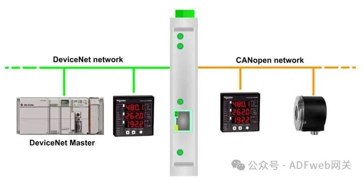
HD67134 – A1 is a CANopen / DeviceNet slave converter. It has the following features:
- Provides triple isolation between CANopen and power, CANopen and DeviceNet, and power and DeviceNet.
- Can be mounted on a 35mm rail (DIN rail);
- Wide power input range: AC 8…24V or DC 12…35V;
- Wide operating temperature range: -40°C to 85°C (-40°F to +185°F).
Configuration
You need to install the Compositor SW67134 software on your computer to perform the following operations:
- Define the parameters of the CANopen line;
- Define the parameters of the DeviceNet line;
- Define the SDO server information;
- Define the SDO client information;
- Define the PDO information (RPDO/TPDO);
- Update the device.
2, New Configuration / Open Configuration: The “New Configuration“ button will create a folder containing the configuration information for the entire device. The device configuration can also be imported or exported: To clone the programmable “CANopen / DeviceNet slave converter“, the folder and all its contents must be retained; To clone a project for a different version of that project, simply copy the project folder and rename it, then open the new folder using the “Open Configuration“ button.
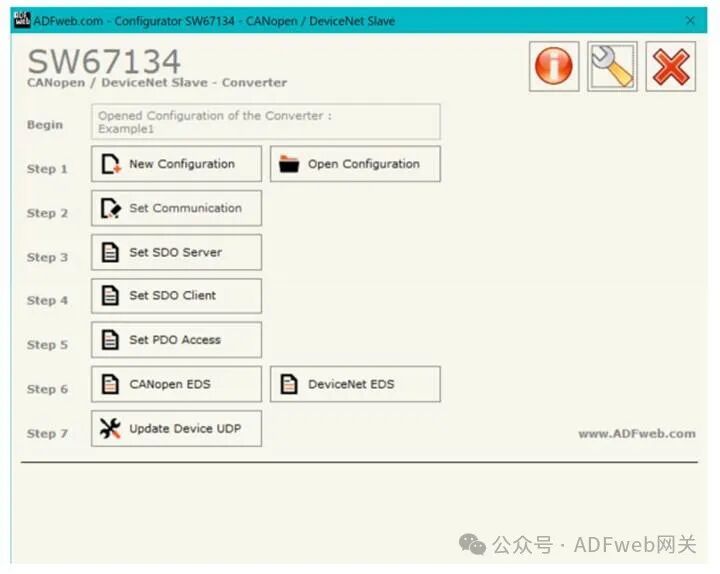
3, Communication Settings
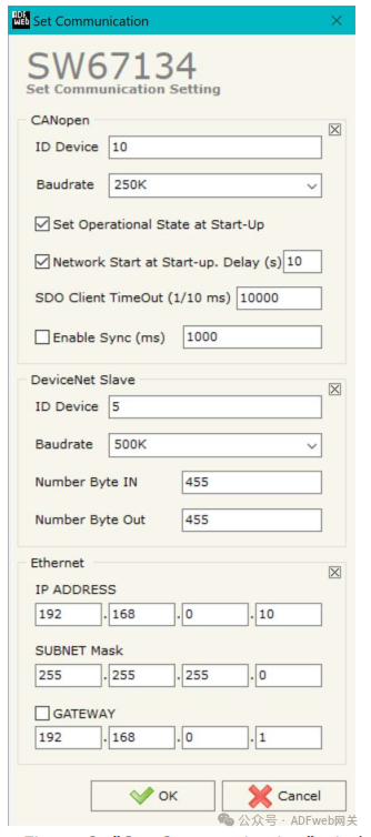
This section defines the basic communication parameters for the two buses (CANopen and DeviceNet).
In the main window of SW67134, click the “Set Communication“ button (Figure 2), and the “Set Communication“ window will pop up (Figure 3).
In the “CANopen” section, the meanings of each field are as follows:
- In the “Device ID” field, define the CANopen endpoint’s ID;
- In the “Baud Rate“ field, define the data transmission rate for the CANopen line;
- In the “Set to Run State on Startup“ field, define the CANopen state. That is: if this option is checked, the board will start in run state; if unchecked, it will start in pre-operational state;
- In the “Start Network on Startup“ field, define the CANopen network state. That is: if this option is checked, the board will send a command after the time defined in the “Delay“ field to set all devices in the network to run state;
- In the “Delay (seconds)“ field, define the delay time before sending the CANopen “Start“ command;
- In the “SDO Client Timeout (1/10 ms)“ field, define the maximum time the device waits for a response from the queried slave;
- If checked, the “Enable Sync (ms)” field and define the time, the converter can periodically send sync messages to the CANopen network.
In the “DeviceNet Slave” section, the meanings of each field are as follows:
- In the “Device ID” field, define the address of the DeviceNet endpoint;
- In the “Baud Rate“ field, define the baud rate for the DeviceNet endpoint;
- In the “Input Byte Count“ field, define the number of bytes from DeviceNet to the gateway (up to 455 bytes);
- In the “Output Byte Count“ field, define the number of bytes from the gateway to DeviceNet (up to 455 bytes).
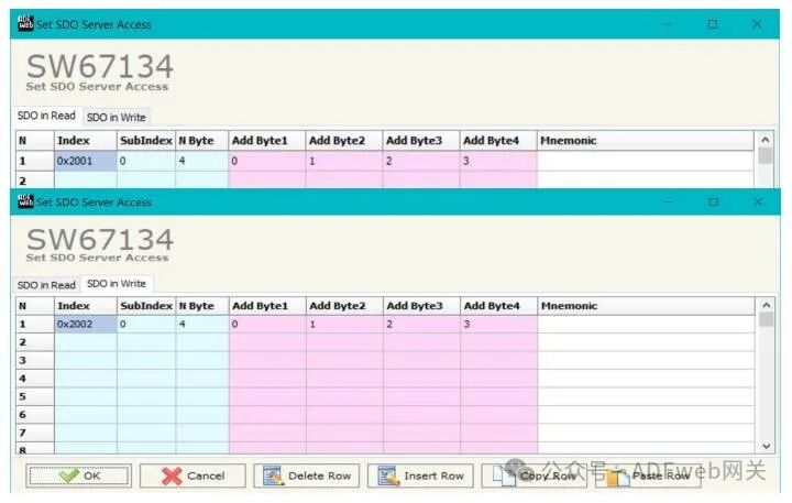
3 Set SDO Server: In the main window of SW67134 (Figure 2), press the “Set SDO Server“ button, and the “Set SDO Server Access Rights“ window will pop up (Figure 4). This window is used to create SDOs for reading or writing on the CANopen side and specify which bytes are associated with these SDOs. The window is divided into two parts: “Read SDO“ and “Write SDO“. The first part is used to read data from the DeviceNet slave via SDO; the second part is used to write data to be sent to the DeviceNet slave via SDO. The meanings of the columns are as follows: In the “Index“ field, define the address of the SDO; in the “Sub-index“ field, define the second address of the SDO; if there is an N bytes field, define the size of the SDO (can be 1, 2, or 4); in the “Add Byte 1“ field, insert the address of the DeviceNet array for the first byte to read/write the SDO; in the “Add Byte 2“ field, insert the address of the DeviceNet array for the second byte to read/write the SDO (only needed when N bytes is 2 or 4); in the “Add Byte 3“ field, insert the address of the DeviceNet array for the third byte to read/write the SDO (only needed when N bytes is 4); in the “Add Byte 4“ field, insert the address of the DeviceNet array for the fourth byte to read/write the SDO (only needed when N bytes is 4); in the “Mnemonic“ field, define the description of the SDO.
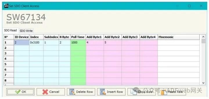
4, Set SDO Client: In the main window of SW67134, click the “Set SDO Client“ button (Figure 2), and the “Set SDO Client Access Rights“ window will pop up (Figures 5a and 5b). Through the SDO client, the HD67134 gateway can read and/or write data from other devices connected to the CANopen network. The window is divided into two parts: “SDO Read“ and “SDO Write“. The first part is used to read data from other devices using SDO and store this data in the DeviceNet array. The second part is used to write existing data from the DeviceNet array to other CANopen devices. The meanings of the data in the “SDO Read” column are as follows: In the “DeviceID” field, enter the device ID to read; In the “Index“ field, define the address of the SDO; in the “Sub-index“ field, define the second address of the SDO; in the “N bytes“ field, define the size of the SDO (can be 1, 2, or 4); in the “Polling Time“ field, enter the loop time for issuing this request; In the “Add Byte 1“ field, define the address in the DeviceNet array where the first byte read by the SDO will be copied; In the “Add Byte 2“ field, define the address in the DeviceNet array where the second byte read by the SDO will be copied (only when N bytes is 2 or 4); in the “Add Byte 3“ field, define the address in the DeviceNet array where the third byte read by the SDO will be copied (only when N bytes is 4); in the “Add Byte 4“ field, define the address in the DeviceNet array where the fourth byte read by the SDO will be copied (only when N bytes is 4); in the “Mnemonic“ field, define the description of the SDO.