Characteristic Impedance
Characteristic Impedance (Z0) is an important parameter in transmission line theory, reflecting the impedance that transmission lines present to the propagation of electromagnetic waves. The characteristic impedance of PCB traces is related to the trace width, spacing, thickness, dielectric thickness, and dielectric constant. Since space can also be considered a type of medium, there are certain differences in the calculation of characteristic impedance for microstrip lines on the surface of the PCB and strip lines in the inner layers of the PCB.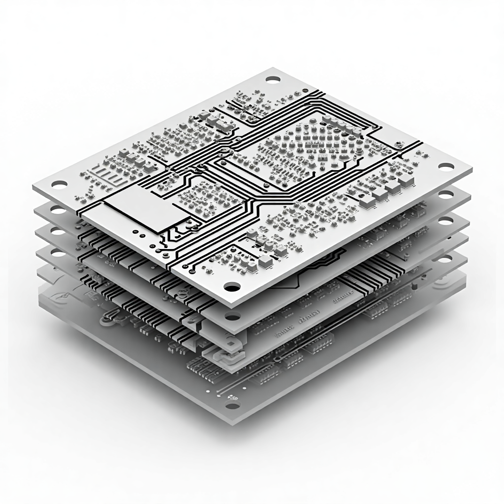 This article summarizes the calculation formulas for the characteristic impedance of different types of PCB traces. You can also obtain a small tool for calculating the characteristic impedance of PCB traces by replying “PCB Trace Characteristic Impedance Calculation Method” on our public account.Note: The following formulas have certain applicable ranges and are only valid when the ratio of trace width to spacing is between 0.1 and 2.0, and the dielectric constant is between 1 and 15. All length units should be converted to mil for calculation; if the trace thickness is in ounces, you can estimate using a width of 1.378 mil for 1 ounce of trace thickness.
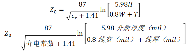
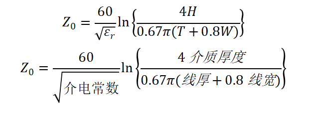
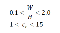 The formula for the characteristic impedance of a standard single-ended microstrip line is as follows:
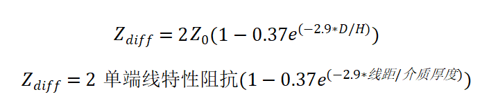
 The formula for the characteristic impedance of a standard differential microstrip line is as follows:
 The formula for the characteristic impedance of a standard single-ended strip line is as follows:
 The formula for the characteristic impedance of a standard differential strip line is as follows: