Big Cat says:
This is a translation of Chapter 13 from the compilation RFSoC-Book, which is detailed in the first article of this series.
“An open-source masterpiece, ‘Software Defined Radio Based on Zynq UltraScale+ RFSoC'”
Mr. Big Cat, WeChat public account: Mr. Big Cat’s Little Bookshelf, an open-source masterpiece, ‘Software Defined Radio Based on Zynq UltraScale+ RFSoC’
Previously, we reviewed the characteristics of RFSoC devices and the theoretical foundations of SDR system design and implementation. The Notebook Sets provide users with opportunities to run, learn, and experiment with examples on RFSoC devices—examples based on theory can also be executed directly in the notebook environment.This chapter will explore the components, tools, and processes required to design RFSoC software-defined radio (SDR) systems from a practical perspective. There are various feasible design workflows for RFSoC SDR systems, and users can choose their preferred working method: whether using AMD tools and/or third-party development tools, adopting low-level or high-level design abstractions, or employing different design inputs and integration methods, there are corresponding solutions available. In addition to outlining the main options for hardware, software, and hardware-software co-design, this chapter will also share some practical experiences from our SDR design solutions and demonstration systems based on the RFSoC platform and PYNQ (Python Productivity for Embedded Computing Framework).
High-Level Design Workflow
RFSoC devices consist of two main customizable parts: the Processing System (PS) and the Programmable Logic (PL). When designing systems for RFSoC, the first consideration is how to partition design functions between these two parts. For example, is data generation or processing done on the PS, or is it entirely executed on the PL? While FPGAs (Field Programmable Gate Arrays) can efficiently accelerate digital signal processing (DSP) algorithms, other processes may be better suited to run on the PS. Determining how and where to partition these functions is an important first step in the design process.
RFSoC integrates hard IPs for RFDC (RF Data Converter) and SD-FEC (Soft-Decision Forward Error Correction). Both are connected to the PL, but there are two control methods: one is controlled by the PL through hardware logic interfaces, and the other is controlled by the PS through software drivers (suitable for any custom or licensed IP included in the PL design). In some applications, if latency is a critical issue, configuring these IP cores from the PL may be the ideal choice. However, for SDR designs that may require frequent reconfiguration, using software drivers on the PS may be more appropriate.
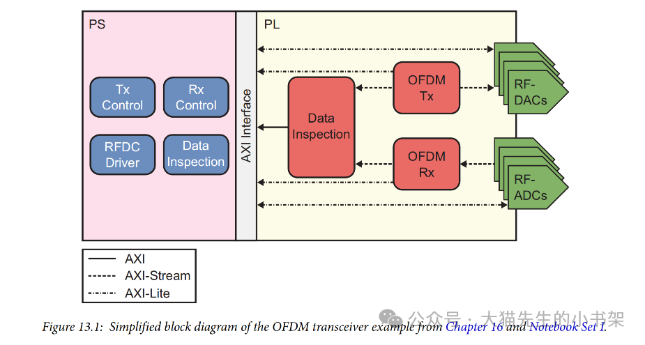
As a high-level preview of a key design in the subsequent chapters of this book (Chapter 16 and the Notebook Set I featuring the Orthogonal Frequency Division Multiplexing (OFDM) transceiver), we will analyze how its functions are partitioned between the PS and PL. This transceiver includes both transmitter and receiver processing functions, as well as additional features for demonstration purposes. The transmitter generates random data, which is then converted into OFDM signals and sent to the RF-DAC; the receiver performs the reverse process, receiving data from the RF-ADC, conducting OFDM reception processing, and recovering the original data. Both the transmitter and receiver logic also require control inputs to support modifications of configuration parameters. Additionally, data monitoring occurs at multiple nodes along the transmit and receive paths.
Figure 13.1 shows a simplified block diagram of the OFDM transceiver model, illustrating the partitioning of these processes between the PS and PL. From the figure, it can be seen that data and signal processing are primarily executed on the PL, while the PS is mainly used for control. Furthermore, the data checking process is divided between the PS and PL. The choice to partition these functions in this manner is closely related to the software used to develop the system and its intended use as a teaching tool.
 The following sections will explore various software tools and design methods used for developing PL (Programmable Logic) and PS (Processing System), and will detail the design processes adopted for several designs in this book.