liwen01 2025.11.08
Introduction
Let us analyze a simple application scenario: a smartwatch and a pair of Bluetooth headphones that are both connected to a mobile phone.
The smartwatch requires the following functionalities:
- Real-time display of phone calls/messages notifications (low-latency signal transmission)
- Synchronization of health data (such as heart rate, steps, sleep, etc.)
- Control music playback (audio control commands)
- Firmware upgrade for the watch (OTA data transmission, larger data volume)
The Bluetooth headphones require the following functionalities:
- Music playback/phone control (control commands)
- Voice communication for phone calls (voice calls)
- Music playback (music data stream)
In the above scenario, there are various types of data: message notifications, health data, music control, firmware upgrade packages, voice calls, etc., each with different requirements for real-time performance and reliability (whether retransmission is needed).
On the mobile phone side, the Bluetooth needs to address the following issues:distinguishing different applications, transferring large files, ensuring data real-time performance and reliability.
To solve the above problems, Bluetooth has the <span>L2CAP</span> (Logical Link Control and Adaptation Protocol).
L2CAP mainly aims to achieve: multi-protocol coexistence, smooth large data flow, and high reliability transmission.
In the above scenario, the overall framework on the mobile phone side is as follows:
Mobile Phone (Central)
│
├── ACL Link #1 → Smartwatch (Peripheral #1)
│       ├── L2CAP Channel #1: ANCS (Call/message notifications)
│       ├── L2CAP Channel #2: GATT (Health data synchronization)
│       ├── L2CAP Channel #3: AVRCP Control (Music control commands)
│       └── L2CAP Channel #4: OTA (Firmware upgrade)
│
└── Bluetooth Headphones (Peripheral #2)
        ├── ACL Link #2
        │       ├── L2CAP Channel #1: A2DP (Music data stream)
        │       ├── L2CAP Channel #2: AVRCP (Playback/phone control)
        │
        └── SCO / eSCO Link #3
                └── HFP (Real-time voice calls)
The smartwatch and Bluetooth headphones are two peripherals of the mobile phone’s Bluetooth, and these two peripherals establish several different links with the phone, each with multiple L2CAP channels.
(1) L2CAP Architecture
The core task of L2CAP is to:efficiently, securely, and orderly transmit upper-layer application data over Bluetooth links.
First, we need to understand what types of links Bluetooth has and the role and position of L2CAP in the Bluetooth protocol stack.
(1) Types of L2CAP Links
In Bluetooth, there are mainly three types of links:ACL, SCO, ISO
ACL (Asynchronous Connection-Less Link):Asynchronous, connectionless data link used for transmitting general data information between master and slave devices
SCO (Synchronous Connection-Oriented Link):Synchronous, connection-oriented link specifically designed for voice transmission (audio)
ISO (Isochronous Link):New type of synchronous link introduced in Bluetooth Low Energy (LE), supporting LE Audio and multi-device broadcast audio
In L2CAP, it only handles ACL links, which are the main channels for data transmission. SCO and ISO real-time data with high requirements do not pass through L2CAP.
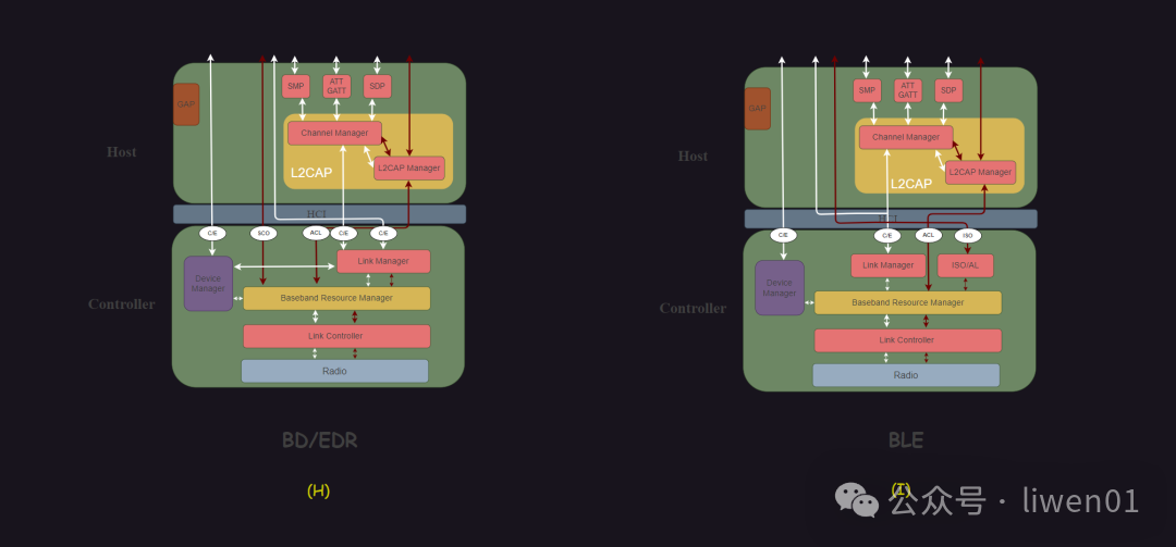
From the core system architecture diagram of Bluetooth, L2CAP is located in the Bluetooth Host, and in addition to processing data from ACL links, it also handles C/E data communication with the controller.
(2) Position and Function of L2CAP
L2CAP is positioned between upper-layer applications and the controller HCI
Upper Layer: such as ATT, SM, SDP, RFCOMM, AVDTP, etc.;
Lower Layer (HCI): the controller, including baseband and link manager.
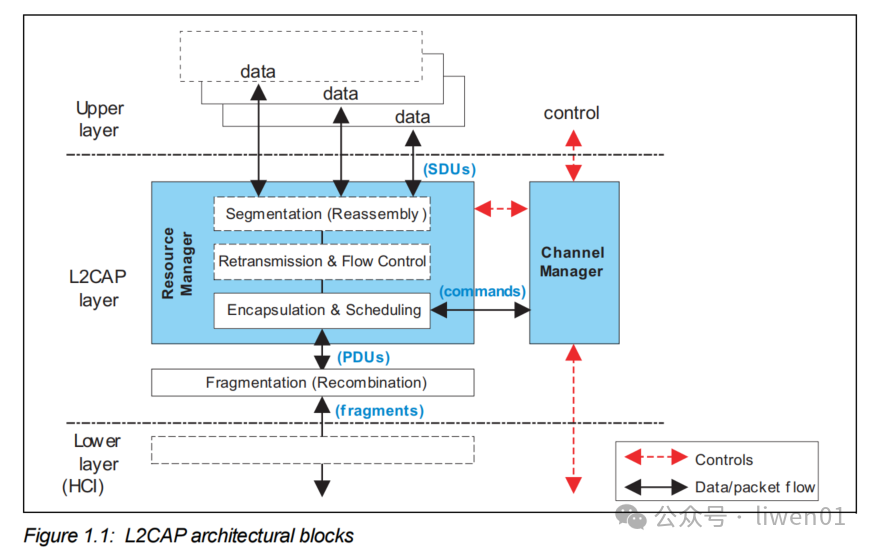
Main functions of L2CAP:
L2CAP is responsible for:data segmentation and reassembly, flow control, retransmission control, multi-channel management, and protocol multiplexing.
It provides logical channel services for upper-layer protocols and adapts to lower-layer physical links.
In the above diagram, there are three types of packets:
SDU (Service Data Unit): The packet of data handed to L2CAP by the upper-layer application
PDU (Protocol Data Unit): The logical packet encapsulated by L2CAP
Fragments: The L2CAP PDU is further fragmented before transmission to fit the lower-layer link
(2) L2CAP Channels and CID
L2CAP channels are virtual data pipelines in the Bluetooth protocol stack.
They provide independent transmission channels for different upper-layer protocols (such as GATT, RFCOMM, A2DP) over the physical ACL link and are responsible for data fragmentation, reassembly, and flow control.
Each channel is uniquely identified by a <span>Channel Identifier</span> (CID), and both communicating parties have their own CID (Local CID / Remote CID)
(1) Functions of L2CAP Channels
Multiplexing: Multiple L2CAP Channels can exist on the same ACL link. Each upper-layer protocol (such as SDP, ATT, RFCOMM) corresponds to an independent channel.
Segmentation & Reassembly: Data larger than the maximum length of the lower-layer packet (MTU) is divided into multiple fragments for transmission and reassembled at the receiving end.
Flow Control and QoS: Different channels can have different priorities, latency requirements, or transmission modes.
Protocol Isolation: Data from different upper-layer protocols do not interfere with each other.
(2) Types of L2CAP Channels
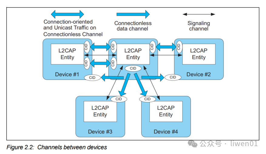
In L2CAP, there are three types of channels:<span>Signaling Channel</span>, <span>Connectionless Channel</span>, <span>Connection-oriented Channels</span>.
(A) Signaling Channel: Each device has at least one signaling channel (CID=0x0001), which is used to transmit control information for L2CAP
- For example: connection request (
<span>Connection Request</span>), configuration request (<span>Configuration Request</span>), disconnection request (<span>Disconnection Request</span>).
(B) Connection-oriented Channel: This is the most commonly used channel type, which establishes unicast bidirectional communication between two devices after connection, with each end of the connection assigned a CID
- Commonly used for transmitting data of high-level protocols such as ATT (GATT layer), RFCOMM, SDP, etc.
(C) Connectionless Data Channel: This channel does not require a prior connection and is suitable for one-to-many broadcast communication; all devices share a common Connectionless Channel CID (0x0002);
- Typical application: Broadcasting of SDP (Service Discovery Protocol)
(3) CID of L2CAP Channels
In L2CAP, each logical channel has a unique channel identifier CID.
The CID of L2CAP is similar to the port number in TCP/IP, used to distinguish different upper-layer protocol or application connections.
(A) CID Value Range and Classification:
CID is a 2-byte value, ranging from <span>0x0001</span> to <span>0xFFFF</span>. However, not all values in these 2 bytes can be used arbitrarily.
According to the Bluetooth specification, some CID values are fixed, while the rest can be dynamically allocated.
| Mode | CID Value | Description |
|---|---|---|
| BR/EDR Fixed Signaling | 0x0001 | L2CAP Control Signaling Channel |
| BR/EDR Connectionless Data | 0x0002 | Connectionless Channel |
| LE Fixed ATT | 0x0004 | ATT Protocol (GATT Layer) |
| LE Fixed L2CAP Signaling | 0x0005 | L2CAP Control Signaling (LE) |
| LE Fixed Security Management | 0x0006 | SMP Protocol Channel |
| Dynamic Channel | 0x0040 ~ … | Dynamic allocation for L2CAP CoC, application data channels, etc. |
In the initial scenario, the CID allocation structure on the mobile phone side may look like this:
Mobile Phone (Central)
│
├── ACL Link #1 (to Smartwatch)
│       ├── CID0x0005 → L2CAP Signaling
│       ├── CID0x0004 → ATT / GATT / ANCS
│       ├── CID0x0043 → AVRCP Control
│       └── CID0x0045 → OTA Channel (Credit-Based)
│
└── ACL Link #2 (to Bluetooth Headphones)
        ├── CID0x0001 → L2CAP Signaling
        ├── CID0x0041 → A2DP Audio Distribution
        ├── CID0x0043 → AVRCP Control
        └── SCO Link → HFP Call (no L2CAP)
In the above diagram, we see that both the Bluetooth headphones and the smartwatch use the same CID 0x0043. Will this cause a conflict?
This brings us to the scope of the CID.
(B) Scope of CID:
The uniqueness of the CID is relative to each physical link (ACL Link), not globally unique across the entire device.
In the above scenario, although both the Bluetooth headphones and the smartwatch use CID = 0x0043, they do not conflict because they are on different physical links (different handles).
In the lower-layer data packets, each ACL data frame carries the corresponding Connection Handle, allowing the upper stack to distinguish which link it belongs to.
(4) Relationship between L2CAP Channel, CID, and Handle
For the application scenario at the beginning of the article, if we add the physical link Handle, the link structure on the mobile phone side would look like this:
Mobile Phone (Central)
│
├── [ACL Link #1] Handle = 0x0001 → Smartwatch (Peripheral #1)
│       ├── L2CAP CID0x0041: ANCS (Call/message notifications)
│       ├── L2CAP CID0x0042: GATT (Health data synchronization)
│       ├── L2CAP CID0x0043: AVRCP Control (Music control commands)
│       └── L2CAP CID0x0044: OTA (Firmware upgrade)
│
└── Bluetooth Headphones (Peripheral #2)
        ├── [ACL Link #2] Handle = 0x0002
        │       ├── L2CAP CID0x0041: A2DP (Music data stream)
        │       ├── L2CAP CID0x0043: AVRCP (Playback/phone control)
        │
        └── [SCO / eSCO Link #3] Handle = 0x0003
                └── HFP (Real-time voice calls)
The mobile phone maintains a total of 3 physical links (Handle=0x0001, 0x0002, 0x0003).
Each ACL link can carry multiple L2CAP Channels, and each Channel is uniquely identified by CID within that link.
(3) L2CAP Channel Operating Modes
L2CAP mainly supports the following operating modes:<span>Basic Mode, Enhanced Retransmission Mode, Streaming Mode, LE Credit Based Flow Control Mode, Enhanced Credit Based Flow Control Mode</span>
(1) Basic Mode
The characteristics of Basic Mode are:no signaling interaction, no fragmentation confirmation, one send one receive, high efficiency, low latency. It is like a regular road, with no traffic control, where vehicles must be cautious;
All protocols such as ATT, SDP, SM (Security Manager) are based on this mode
(2) Enhanced Retransmission Mode
ERTM characteristics include:guaranteed ordered transmission, selective retransmission mechanism, flow control, timeout and window mechanism (TxWindow)
It is like a city arterial road with traffic lights, ensuring every vehicle arrives safely, but at a slightly slower speed;
It is still widely used in BR/EDR classic Bluetooth. Mainly applied in: AVCTP (A/V Remote Control), OBEX (file transfer), and custom profiles requiring reliability
(3) Streaming Mode
Streaming Mode characteristics include:no retransmission of lost data (suitable for real-time streams), but flow control is present; if a packet is lost, it is discarded directly without blocking subsequent transmissions.
It is like a highway, allowing a few vehicles to break down, but traffic flows smoothly;
It is mainly applied in: A2DP audio streaming, real-time video transmission (such as BT video extension)
(4) LE Credit Based Flow Control Mode
LE Credit Mode characteristics include:specifically designed for BLE use, no longer using complex retransmission mechanisms; the sender consumes “credits”; the receiver controls flow by increasing credits; each connection has a unique CID (0x0040 ~ 0x007F).
It is mainly applied in: BLE data channels (such as custom services outside GATT)
(5) Enhanced Credit Based Flow Control Mode
Enhanced Credit Mode is a mode introduced in Bluetooth 5.2, a new generation mode shared by BR/EDR and LE, supporting parallel transmission of multiple L2CAP channels; it operates on ISO links.
It is like a multi-track high-speed train system, capable of parallel transmission of multiple data streams while synchronizing.
Its emergence aims to replace the traditional ERTM / Streaming modes
It supports:flow control, fragmentation/reassembly, optional reliability, and multi-stream synchronization (for audio synchronization scenarios).
(4) L2CAP State Machine
How do the various modes and channels introduced above coordinate their work in L2CAP?
In L2CAP, the lifecycle of logical channels (L2CAP Channels) is managed through a state machine. For example, the state of the control channel transitions from creation, configuration, data transmission to release.
It is important to note that the state machine only applies to bidirectional CID channels.
(1) Three Elements of the State Machine
The three elements of the state machine are:state, event, action
State: The current phase of the channel, such as CLOSED, OPEN, etc.
Event: External or internal actions that trigger state changes, such as receiving requests, timeouts, etc.
Action: Operations executed when a specific event occurs, such as sending a response, setting a timer, etc.
(2) Working Principle of the State Machine
The operation of the L2CAP state machine is based on an event-driven mechanism:
State + Input Event → Action + Next State
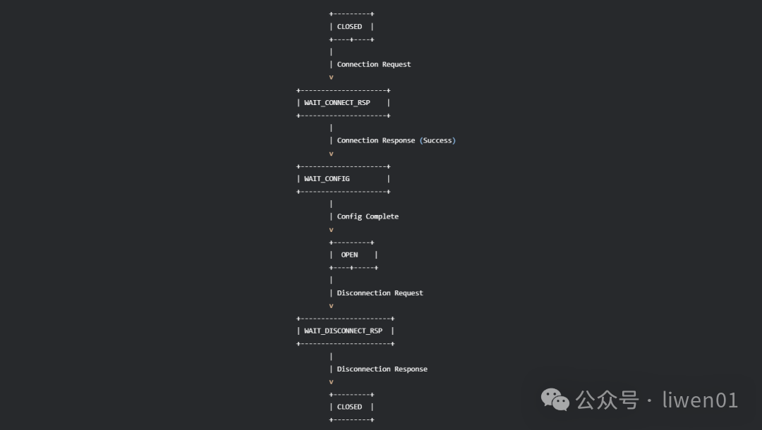
For example, a typical workflow:
CLOSED → WAIT_CONNECT_RSP → WAIT_CONFIG → OPEN → WAIT_DISCONNECT_RSP → CLOSED
CLOSED State: Indicates that the channel has not been established or has been released.
WAIT_CONNECT_RSP State: Indicates that it is waiting for a response from the remote end <span>Connection Response</span>.
WAIT_CONFIG State: Indicates that the connection has been established, and both parties begin to negotiate configuration.
OPEN State: Indicates that the channel has been established and configured, and data transmission can occur.
WAIT_DISCONNECT_RSP State: Indicates that a disconnection request has been sent, waiting for a response from the remote end.
The overall process is as follows:
(3) Types of State Machines
The L2CAP protocol does not have just one state machine, but contains multiple functional state machines, each responsible for different parts.
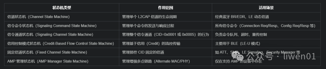
The core one is the channel state machine, which controls the complete lifecycle of a logical channel (CID) from creation → configuration → transmission → disconnection.
How do these state machines work together?
Below is an example of the working relationship between a channel state and a signaling channel state machine.
When an event (such as “Disconnection Request”) arrives:
- First, the Signaling Channel state machine parses it;
- Find the target channel (based on CID);
- Forward it to the corresponding Channel state machine;
- The state machine executes actions (such as releasing resources) and switches states;
- If a response is needed, it is sent by the signaling channel state machine.
In other words:Signaling Channel manages control flow, Channel State Machine manages data flow.
(5) L2CAP Packet Format
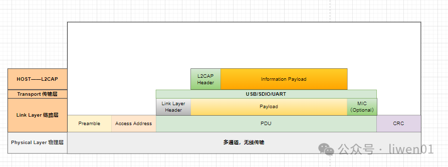
Overall, the L2CAP packet consists of: Header + Payload. However, under different connection modes in L2CAP, their message formats differ.
Therefore, L2CAP has multiple packet formats.
(1) Basic L2CAP Data Packet
The Basic L2CAP Data Packet is the most basic and common L2CAP data format, used for ordinary data channels in BR/EDR and LE-U.
It does not support fragmentation, reassembly, retransmission, and flow control, making it simple and efficient.
Its packet format is as follows:
| Length (2B) | CID (2B) | Payload (N bytes) |
- Length: Indicates the number of bytes from
<span>CID</span>to the end of the data (excluding the<span>Length</span>field itself). - CID: Identifies which L2CAP channel this data belongs to (e.g., 0x0040 → ATT, 0x0004 → SDP).
- Payload: Upper-layer protocol data (such as SDP, RFCOMM, ATT, SMP, etc.).
(2) L2CAP Signaling Packet
It is used for control and management at the L2CAP layer, not for transmitting upper-layer data. Common commands include:establishing channels, parameter configuration, disconnecting channels, testing links.
All control processes are completed through this signaling channel (CID=0x0001). Its data format is as follows:
| Length (2B) | CID (2B) | Code (1B) | Identifier (1B) | Command Length (2B) | Command Data (N bytes) |
- CID: Fixed to 0x0001 (L2CAP Signaling Channel).
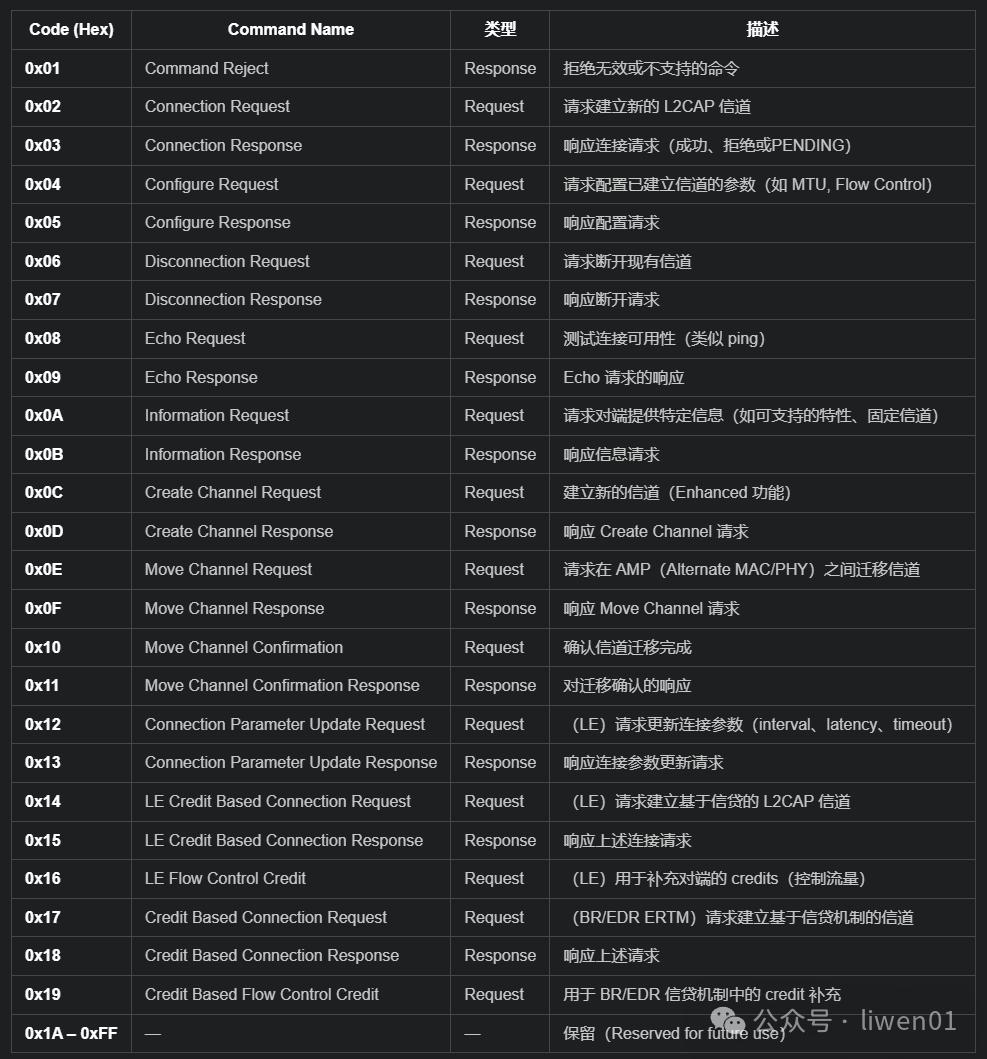
- Code: Indicates the signaling command type (e.g.,
<span>0x02</span>: Connection Request,<span>0x03</span>: Connection Response). - Identifier: Used to match requests and responses.
- Command Length: Length of command parameters.
- Command Data: Specific parameter content of the command (such as target CID, MTU, PSM, etc.).
The above Code indicates different signaling command types, which are defined in L2CAP as follows:
(3) Enhanced Retransmission / Flow Control Mode Packet
It is used for BR/EDR L2CAP connection-oriented channels.
Supports:ordered transmission, segmentation and reassembly (SAR), retransmission and acknowledgment mechanisms, flow control management
Its data format is as follows:
| Length (2B) | CID (2B) | Control (2B) | Payload (N bytes) |
Control Field Structure (16 bits) includes the following subfields:
- SAR (2 bits): Fragmentation control (00: unsegmented, 01: start, 10: continuation, 11: end)
- ReqSeq (7 bits): Expected next sequence number
- Final (1 bit): Indicates whether it is the last frame
- TxSeq (6 bits): Sequence number of the current packet
Payload: The content of the fragmented L2CAP SDU.
(4) LE Credit-Based L2CAP Data Packet
It is used only for Bluetooth Low Energy (LE-U) physical links, controlling flow through the Credit mechanism instead of relying on retransmission.
It does not require complex fragmentation control fields, making it efficient, commonly used in LE Audio, LE Mesh, GATT over L2CAP, and other new LE applications.
The data format is as follows:
| Length (2B) | CID (2B) | SDU Data (N bytes) |
- CID: Dynamically allocated LE channel (range: 0x0040 ~ 0x007F).
- SDU Data: Upper-layer protocol data (complete SDU, not fragmented).
(5) LE Credit-Based Control Packet
It is the command format for the LE signaling channel (CID = 0x0005), transmitted only on the LE signaling channel (0x0005)
Used for establishing, configuring, and managing LE Credit-Based Channels
Its command format is as follows:
| Code (1B) | Identifier (1B) | Length (2B) | Command Parameters (N bytes) |
Code: Command type (e.g., 0x14: LE Credit Based Connection Request).
Command Parameters: Command parameters, such as:
<span>LE PSM</span>(LE Protocol/Service Multiplexer)<span>Source CID</span>/<span>Destination CID</span><span>MTU</span>,<span>MPS</span>,<span>Initial Credits</span>, etc.
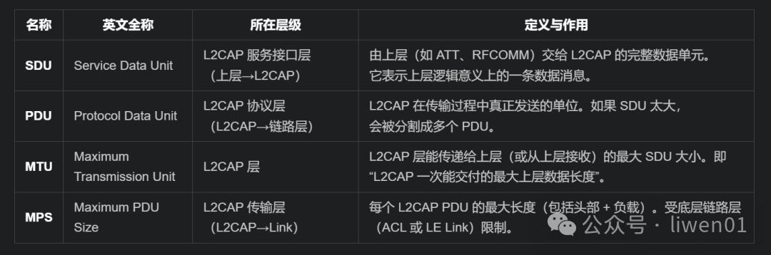
(6) SDU, PDU, MTU, MPS in Packets
-
SDU is the complete message passed down from the upper layer,
-
PDU is the actual sentdata fragment
-
MTU limits the maximum size of the SDU
-
MPS limits the size of a single PDU
Their definitions are as follows:
Their structural diagram is as follows:
┌────────────────────────────────────────────┐
│ Upper-layer protocol data (such as ATT, RFCOMM, SDP)       │
│           ↑ ↓                             │
│           L2CAP Service Interface          │
│           ↑ ↓                             │
│ L2CAP SDU (Service Data Unit)            │  ← Maximum length limited by MTU
│           │                               │
│    [Segmentation]                │
│           ↓                               │
│ ┌──────────────┬──────────────┬──────────┐ │
│ │ L2CAP PDU #1 │ L2CAP PDU #2 │ L2CAP PDU #3 │  ← Each length ≤ MPS
│ └──────────────┴──────────────┴──────────┘ │
│           ↓                               │
│    Sent to link layer (HCI ACL / LE Link)       │
└────────────────────────────────────────────┘
Conclusion
This article introduced L2CAP (Logical Link Control and Adaptation Protocol) as the multiplexing and data scheduling center of the Bluetooth protocol stack.
In the next article, we will briefly introduce Bluetooth application protocols and then analyze the working principles of Bluetooth pairing process.
——————End——————For more content, please followliwen01 public account