Skip to content
With the development of automotive intelligence and connectivity, cars are no longer just simple means of transportation. Car owners are beginning to focus on and expect OEMs to maintain and upgrade their vehicles remotely, just like mobile phone software updates, to enhance their driving experience and access new features. At the same time, OEMs, in order to reduce the recall risks caused by software vulnerabilities and to iterate new features, actively utilize remote diagnostic technology to build automotive OTA upgrade systems, achieving comprehensive OTA refresh applications. This article mainly introduces automotive OTA and remote diagnostic technology, and proposes a design scheme for remote diagnostics in automotive OTA refresh, providing guidance for OTA upgrades and fault diagnosis.
The automotive OTA function has become a hot topic nowadays. New car manufacturers represented by Tesla have successfully introduced “over-the-air download technology” from the consumer electronics field into the automotive sector, leading to a global pursuit by many OEMs, while also overturning traditional perceptions of vehicles. OTA upgrades provide OEMs with a quicker and more cost-effective update method than traditional diagnostic tools, enhancing user experience and brand loyalty. Behind these benefits is the support of OEM remote diagnostic technology. This article will introduce a design scheme for remote diagnostics in automotive OTA refresh, mainly including the overall architecture and diagnostic requirements of the OTA cloud, the design of the onboard terminal network diagnostic architecture, software storage and refresh strategies, and remote fault diagnosis.
01 Introduction to Automotive OTA
OTA (Over-the-Air Technology) refers to “over-the-air download technology”. Similar to the common scenario of updating firmware (software) on mobile phones, vehicles can also achieve remote updates of the internal firmware (FOTA) and software data (SOTA) of various controllers through wireless networks. This is known as automotive OTA technology.
What benefits can the automotive OTA upgrade system actively built by OEMs bring?
1) OTA can quickly upgrade and repair software code defects. With the rapid iteration of vehicle function configurations in the market, OEMs are forced to shorten the overall vehicle development cycle, and the risk of vehicle recalls due to software vulnerabilities continues to rise. Currently, the total code volume of high-end vehicles has surpassed 100 million lines. Even if developed according to the highest software standards of Capability Maturity Integration Model Level 5, there is still a 0.32% code defect rate. Using OTA upgrades can reduce OEMs’ vehicle repair costs by 50%.
2) OTA brings a new “marketing model” to OEMs. The emergence of the concept of “software-defined vehicles” (SDV) has brought tremendous changes to the traditional hardware selling model of automobiles. Vehicles that have already been sold can still enable certain “upgrade packages” through software payment methods, such as Tesla’s Full Self-Driving (FSD) upgrade package. According to statistics, the annual compound growth rate of the software customization market is expected to be about 30% over the next five years, and the global automotive software customization market size is expected to reach 27.542 billion yuan in 2023. Therefore, the potential and benefits of software that OEMs can upgrade via OTA are considerable. As shown in Figure 1:
Figure 1 Global Automotive Software Customization Market Size and Growth Rate
3) Through OTA, OEMs can improve the experience of vehicle dynamics, braking, range, human-machine interaction systems, and intelligent driving assistance systems. This enhances the overall performance and functionality of vehicles, increases the novelty for car owners, and boosts their brand loyalty.
While automotive OTA brings numerous benefits, it also poses new challenges for OEMs. Whether it is the design of the OTA cloud architecture, information security, backend software version control, or the onboard network diagnostic architecture design, remote fault diagnosis, OTA refresh process, ECU software refresh strategies, etc., OEMs need to fully consider and thoroughly test and validate to avoid the phenomenon of “vehicle paralysis” after OTA push, leading to adverse experiences for car owners.
02 Automotive Remote Diagnosis
Automotive remote diagnosis refers to a diagnostic technology that relies on the vehicle’s mobile communication capabilities (WIFI/4G/5G) to complete remote control and diagnostic operations by the OEM’s backend (or mobile app) without the need for the vehicle to be returned to the dealership. Remote OTA refresh is one application scenario of remote diagnostics. In addition, remote diagnostic technology, through integration with cutting-edge technologies such as IoT, big data, and cloud computing, can also provide important support for OEMs in R&D testing, production line electrical testing, and after-sales diagnosis.
First, remote diagnosis can collect data online, reducing development cycles and costs. During the R&D phase, vehicles require extensive road tests and durability tests, and the data collection equipment on test vehicles is limited. Through remote diagnosis, vehicle fault phenomena that occur during testing can be promptly fed back to R&D personnel for analysis and simulation, quickly assisting in resolving fault issues.
Secondly, remote diagnosis can achieve initialization and function testing across workstations during production line electrical testing, and perform OTA refreshes, enabling customized production of automotive software to meet car owners’ customization needs.
Finally, remote diagnosis can periodically monitor vehicle status, diagnose vehicle health in real-time, and conduct vehicle fault warnings through statistical analysis of big data, pushing maintenance and repair guidance suggestions to the OEM’s after-sales dealership.
03 OTA Refresh Remote Diagnosis Design
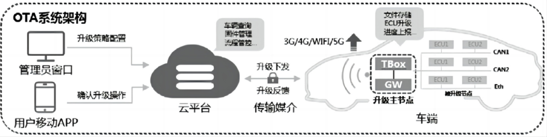
The OTA refresh system architecture mainly consists of three parts: server (cloud platform), transmission medium (3G/4G/WIFI/5G), and onboard terminal (ECU). This article is based on the OTA refresh system architecture design shown in Figure 2, focusing on a detailed introduction to the remote diagnostic scheme for the server (cloud platform) and the onboard terminal (ECU).
Figure 2 OTA Refresh System Architecture
The OTA server, also known as the OTA cloud platform, serves as a connection between users (car manufacturers, car owners) and vehicles during the software refresh process, enabling remote intelligent diagnosis and fault prediction analysis. Generally, the design of the OTA cloud platform is required to be deployed on the OEM’s private server and must support OTA upgrades for multiple vehicle models.
3.1.1 Overall Architecture of OTA Cloud Platform
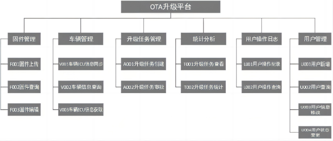
The OTA cloud platform mainly includes modules for user management, firmware management, vehicle management, upgrade task management, statistical analysis management, and user operation log management, as shown in Figure 3.
Figure 3 Overall Architecture of OTA Cloud Platform
The user management module: The OTA cloud platform provides a software system for the OEM, thus requiring a user management module to implement user permission allocation and management. The system setup environment defaults to create a super administrator user, who can log in and perform functions such as adding users, viewing users, and modifying user information in the user management module. The firmware management module: This mainly provides users with firmware upload, query, and editing (version management) functions. Users upload firmware that has passed OEM testing to the OTA cloud platform for upgrade task creation.
The vehicle management module: This mainly includes vehicle ECU information synchronization, vehicle ECU information retrieval, and vehicle information viewing functions. The vehicle ECU information synchronization sub-module interfaces with the OEM’s MES (Manufacturing Execution System) to import different vehicle configuration information for filtering target vehicles and configuring upgrade strategies during OTA upgrades.
The upgrade task management module: This is mainly responsible for providing users with functions for creating upgrade tasks, approving upgrade tasks, querying upgrade tasks, and checking upgrade progress.
The statistical analysis management module: This is mainly responsible for statistically analyzing the execution results of published upgrade tasks. Users can view the success rate of upgrade vehicles corresponding to each upgrade task, the statistics of failure reasons, and the analysis of reasons for unexecuted upgrades.
The user operation log management module: This is mainly responsible for providing super administrator users with records of all functional operations performed by all users who log into the OTA cloud platform.
3.1.2 Diagnostic Requirements of OTA Cloud Platform
The OTA cloud platform must meet high availability, high performance, scalability, and monitorability diagnostic requirements. Specifically, it is reflected in the following aspects:
1) Use a microservices Browser/Server service framework that can support various load balancing modes (service consumers select a service provider from the provider list based on soft load balancing algorithms such as random, weight, polling, least concurrent priority, etc. for remote calls. If the call fails, it must automatically diagnose and switch to another service provider);
2) Three-dimensional monitoring that can provide detailed monitoring of system resources (CPU, load, memory, network, and disk) basic indicators, and perform fault diagnosis and early warning for each service call response time and error rate;
3) The system must have high reliability and high performance, ensuring that the entire business system running on the system can provide customers with 99.9% availability of efficient and high-quality services;
4) Use service cluster management technology, leveraging multiple computers for parallel computing to achieve high performance and redundant backup, allowing the entire system to continue functioning even in the event of a single machine failure;
5) The system must have a fault isolation mechanism, which can limit the impact of faults to a minimum range in case of application software system failures, improving the overall service capability of the system.
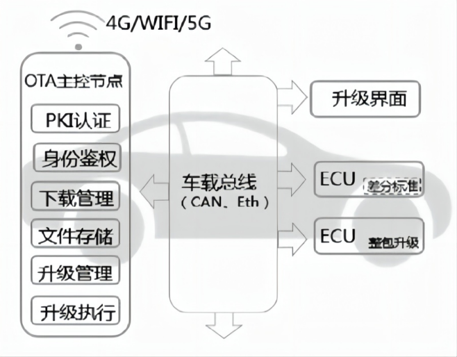
The OTA onboard terminal acts as the executor of the OTA upgrade. Taking OTA push as an example, there are many parts that users can perceive and experience. The design focus of the onboard terminal needs to consider human-machine interaction, network diagnostic architecture design, ECU refresh duration, software storage and refresh strategies, and remote fault diagnosis mechanisms. The onboard terminal network framework is shown in Figure 4, where the OTA master control node is managed by TBOX and the central gateway (GW), and the upgrade interface is managed by the vehicle machine. The refreshed ECU is required to support in-vehicle Ethernet (DoIP) or CAN bus (DoCAN) communication protocols. If the ECU upgrade package is large (e.g., hundreds of megabytes), it needs to support differential data algorithms.
Figure 4 OTA Onboard Terminal Framework
3.2.1 OTA Human-Machine Interaction Design
During OTA upgrades, in addition to the cloud platform pushing upgrade tasks to remind car owners via the app, the vehicle side (vehicle machine or central control) must also cooperate to develop and display some upgrade interfaces (such as upgrade progress, upgrade condition reminders, etc.) to remind car owners of vehicle security and departure cooperation operations.
3.2.2 Network Diagnostic Architecture Design
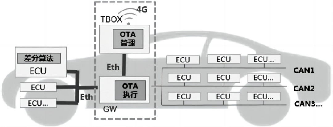
Currently, the vehicle’s main network backbone still mainly uses mature CAN bus communication. However, for ECUs with larger software packages, in order to address refresh duration and other factors, in-vehicle Ethernet technology is used to overcome the bandwidth limitations of the CAN bus, as shown in Figure 10.
The main architecture includes the OTA master control node (TBOX and GW) and the refreshed ECU. TBOX primarily ensures a secure and reliable connection channel with the cloud platform, integrating security modules such as PKI authentication and identity verification. GW mainly manages the connection channels of the internal network and integrates diagnostic refresh machine functions. Depending on the size of the software package and theoretical refresh duration (e.g., not exceeding 20 minutes), the CAN bus topology architecture adds Ethernet interface design, using DoIP protocol for ECU diagnostic refresh.
Figure 5 Network Diagnostic Architecture Diagram
3.2.3 ECU Software Storage and Refresh Strategy
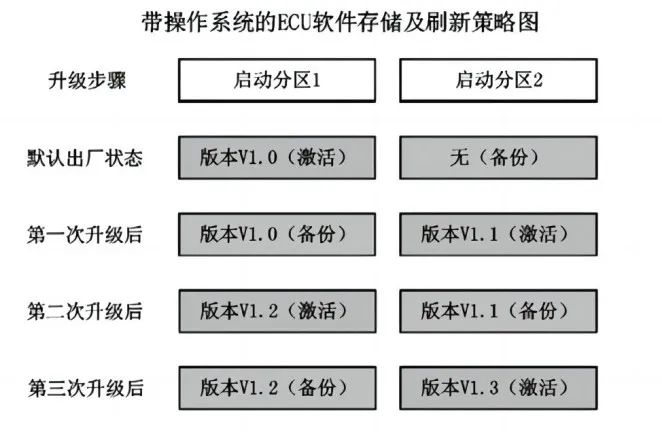
Before OTA refresh, the ECU software upgrade package is issued from the cloud platform to be stored in the memory of the onboard OTA master control node, managed by the file storage module for the overall vehicle software upgrade package and backup package control. The upgrade management module is primarily responsible for controlling the refresh strategy of the refresh machine. OTA refresh requires designing multiple redundant refresh strategies, meaning that after the OTA backend initiates an upgrade task, the OTA master control node refresh machine in the same vehicle usually performs multiple refresh attempts for the same ECU to reduce occasional failure factors and improve OTA refresh success rates. The refreshed ECUs are mainly divided into traditional embedded chip ECUs and complex ECUs with operating systems (such as Linux, Android, AutoSAR). Based on the hardware resource situation of the ECU, we have designed the following ECU internal storage and refresh strategies: For ECUs with operating systems, as shown in Figure 11, hardware storage resources are rich, and two different startup partitions are allocated within the controller. The specific refresh process is as follows:
1) The default factory state activates startup partition 1, running version V1.0, with no backup program in startup partition 2;
2) When the OTA initiates the first V1.1 version refresh request, the refresh data will be stored in the backup partition (partition 2). Upon successful refresh, startup partition 2 is activated, and the backup partition (partition 1) is exchanged. Upon the next power-up, the program will be started by startup partition 2 and operate normally;
3) When the OTA initiates the second V1.2 version refresh request, the refresh data will be stored in backup partition 1. Upon successful refresh, startup partition 1 is activated, and the backup partition (partition 2) is exchanged. Upon the next power-up, the program will be started by startup partition 1 and operate normally;
4) When the OTA initiates the third V1.3 version refresh request, the refresh data will be stored in the backup partition (partition 2). Upon successful refresh, startup partition 2 is activated, and the backup partition (partition 1) is exchanged. Upon the next power-up, the program will be started by startup partition 2 and operate normally.
Thus, the partition refresh is exchanged in a loop. Even if the current startup partition fails to start normally due to refresh failure, the ECU can still start from the backup partition through self-rollback, ensuring that the system operates normally.
Figure 6 ECU Software Storage and Refresh Strategy Diagram with Operating System
For traditional embedded ECUs, a BOOT+APP software architecture is typically used, as shown in Figure 12. The more complex the ECU functionality, the larger the APP capacity of the selected main control chip. To achieve the ECU’s internal software self-rollback function, a portion of the APP space needs to be allocated for software backup storage (e.g., APP2). When the ECU is refreshed, the BOOT code is responsible for guiding the upgrade process, storing the upgrade package in the APP area (generally the program startup entry address space). Since the embedded chip ECU usually has only one program startup entry, if the refresh fails (APP cannot be activated), the BOOT guide program will instruct copying the backup program APP2 to the APP area for rollback and startup, ensuring the ECU operates normally. For ECUs with smaller APP capacities that do not support APP2 space allocation, the OTA master control node must achieve backup storage for the upgrade package.
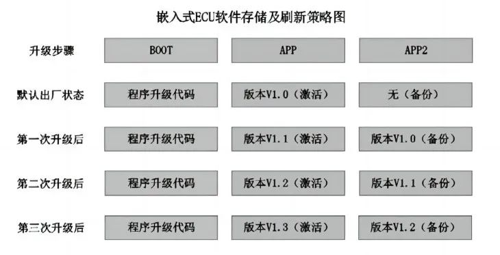 Figure 7 Embedded ECU Software Storage and Refresh Strategy Diagram
3.2.4 OTA Remote Fault Diagnosis Design
Currently, OTA refresh is mainly implemented through diagnostic communication methods for ECU refresh condition checks, refresh process data transmission, and reset reboot after refresh. During the refresh process, if the refreshed ECU cannot ensure the application program runs normally due to entering BOOT or other reasons (except for the non-intrusive refresh method), it is necessary to perform ECU fault masking design in advance to avoid generating fault codes during the refresh process, misleading subsequent remote fault diagnosis and statistical analysis. During the OTA refresh process, diagnostic fault masking can be implemented using the 0x85 (Control DTC Setting) service in the UDS diagnostic protocol. Another challenge in OTA remote fault diagnosis is the conflict with local fault diagnosis. The OTA cloud platform has difficulty identifying local diagnostic devices; therefore, it is essential to integrate arbitration judgment logic for remote and local diagnosis on the vehicle side. The central gateway (GW) is responsible for arbitration coordination. During the OTA refresh process, the gateway masks the local fault diagnosis routing forwarding function. Similarly, when there are local diagnostic devices, the gateway masks the remote fault diagnosis routing forwarding function, with masking being effective only during the current ignition cycle.
The automotive OTA refresh has brought urgent demand and excellent development opportunities for remote diagnostic technology. The OTA upgrade systems and remote diagnostic platforms actively deployed by OEMs are not only for the current repair of software vulnerabilities and rapid function updates but also to adapt to the trend of “software-defined vehicles” (SDV) and the technical development of higher-level autonomous driving. The data accumulated by the OEM’s remote diagnostic platform is a test of its comprehensive ability to combine big data mining with intelligent diagnostic applications. As a “leader,” Tesla has achieved vehicle component fault diagnosis in 90% of cases through remote diagnostic technology, saving car owners one day’s worth of maintenance time each year. Domestic car manufacturers need to catch up quickly to provide car owners with more convenient and satisfactory service experiences, which still requires a long development journey.
Welcome all angel round and A round enterprises in the entire automotive industry chain (including the electrification industry chain) to join the group (Friendly connections with 700 automotive investment institutions, including top-tier institutions; some quality projects will be selected for themed roadshows to existing institutions));There are communication groups for leaders of science and technology innovation companies, automotive industry complete vehicles, automotive semiconductors, key parts, new energy vehicles, intelligent connected vehicles, aftermarkets, automotive investment, autonomous driving, vehicle networking, and dozens of other groups. Please scan the administrator’s WeChat to join the group (Please indicate your company name)
Figure 7 Embedded ECU Software Storage and Refresh Strategy Diagram
3.2.4 OTA Remote Fault Diagnosis Design
Currently, OTA refresh is mainly implemented through diagnostic communication methods for ECU refresh condition checks, refresh process data transmission, and reset reboot after refresh. During the refresh process, if the refreshed ECU cannot ensure the application program runs normally due to entering BOOT or other reasons (except for the non-intrusive refresh method), it is necessary to perform ECU fault masking design in advance to avoid generating fault codes during the refresh process, misleading subsequent remote fault diagnosis and statistical analysis. During the OTA refresh process, diagnostic fault masking can be implemented using the 0x85 (Control DTC Setting) service in the UDS diagnostic protocol. Another challenge in OTA remote fault diagnosis is the conflict with local fault diagnosis. The OTA cloud platform has difficulty identifying local diagnostic devices; therefore, it is essential to integrate arbitration judgment logic for remote and local diagnosis on the vehicle side. The central gateway (GW) is responsible for arbitration coordination. During the OTA refresh process, the gateway masks the local fault diagnosis routing forwarding function. Similarly, when there are local diagnostic devices, the gateway masks the remote fault diagnosis routing forwarding function, with masking being effective only during the current ignition cycle.
The automotive OTA refresh has brought urgent demand and excellent development opportunities for remote diagnostic technology. The OTA upgrade systems and remote diagnostic platforms actively deployed by OEMs are not only for the current repair of software vulnerabilities and rapid function updates but also to adapt to the trend of “software-defined vehicles” (SDV) and the technical development of higher-level autonomous driving. The data accumulated by the OEM’s remote diagnostic platform is a test of its comprehensive ability to combine big data mining with intelligent diagnostic applications. As a “leader,” Tesla has achieved vehicle component fault diagnosis in 90% of cases through remote diagnostic technology, saving car owners one day’s worth of maintenance time each year. Domestic car manufacturers need to catch up quickly to provide car owners with more convenient and satisfactory service experiences, which still requires a long development journey.
Welcome all angel round and A round enterprises in the entire automotive industry chain (including the electrification industry chain) to join the group (Friendly connections with 700 automotive investment institutions, including top-tier institutions; some quality projects will be selected for themed roadshows to existing institutions));There are communication groups for leaders of science and technology innovation companies, automotive industry complete vehicles, automotive semiconductors, key parts, new energy vehicles, intelligent connected vehicles, aftermarkets, automotive investment, autonomous driving, vehicle networking, and dozens of other groups. Please scan the administrator’s WeChat to join the group (Please indicate your company name)