
Abstract
This paper proposes a closed-loop control scheme for the LLC resonant converter based on a Digital Signal Processor (DSP), aimed at optimizing the dynamic response of the converter and improving system stability. By designing appropriate control strategies and feedback loops, combined with the characteristics of the LLC resonant converter, efficient and precise power conversion is achieved. The DSP serves as the core control unit, utilizing its high-speed computing capabilities for real-time adjustments and optimizations. Through MATLAB simulation and experimental validation, this control scheme effectively enhances the system’s anti-interference capability and maintains excellent voltage output stability under varying load and input voltage conditions.
Theory
1. Working Principle of LLC Resonant Converter
-
The LLC resonant converter is a type of resonant DC-DC converter, primarily composed of resonant inductors, resonant capacitors, secondary rectification, and filtering circuits. -
Its working principle is to achieve adaptive regulation of input voltage and load variations by controlling the on-off timing of the switch devices. -
The LLC resonant converter features Zero Voltage Switching (ZVS) and Zero Current Switching (ZCS), significantly reducing switching losses and improving conversion efficiency.
2. Closed-Loop Control Strategy
-
This control scheme monitors the output voltage in real-time, using a PI controller to adjust the output voltage, ensuring stable operation of the system under various working conditions. -
Specifically, the feedback signal is processed by the DSP via an A/D converter, and the DSP adjusts the converter’s switching frequency in real-time according to the preset control algorithm, thus achieving precise control of the output voltage.
3. Application of DSP
-
As the control core, the DSP’s high-speed computing capability allows the closed-loop control to respond quickly at high frequencies and effectively manage disturbances caused by input voltage and load variations. -
The design of the DSP control system includes three parts: signal acquisition, processing, and output, ensuring the real-time performance and accuracy of the control system in dynamic environments.
Experimental Results
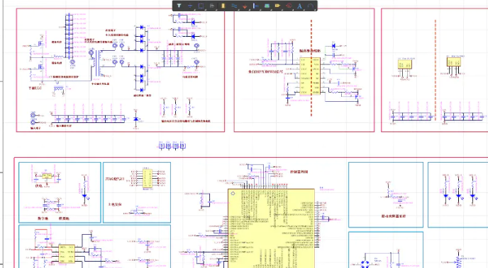
The hardware platform used for the experiments is the TMS320F28335 DSP development board provided by TI, with the main parameters of the converter set as follows: input voltage range of 10V-30V, output voltage of 12V, and maximum output power of 100W. The experimental results indicate that the DSP-based closed-loop control scheme effectively stabilizes the output voltage, and under varying input voltage and load changes, the system can quickly respond and return to a steady state.
1. Steady-State Response
Under constant input voltage, the experiment measured the converter’s output voltage stabilizing at 12V, with a smooth output waveform and no significant fluctuations, meeting design requirements.
2. Dynamic Response
When the input voltage changes from 20V to 30V, the converter can stabilize the output voltage within 50ms without significant overshoot. During load changes, the system can also quickly return to normal operation, demonstrating the rapid response capability of the closed-loop control system.
3. Efficiency Testing
At a load of 60W, the system achieved a maximum efficiency of 92%, validating the high efficiency of the design scheme.
Sample Code
% Define system parameters
Vin = 20; % Input voltage
Vout = 12; % Output voltage
L = 1e-6; % Resonant inductor
C = 1e-6; % Resonant capacitor
R = 10; % Load resistance
f_switch = 100e3; % Switching frequency

% PI controller parameters
Kp = 0.1; % Proportional gain
Ki = 0.05; % Integral gain

% Initial conditions
Vout_measured = 11.8; % Measured output voltage
error = Vout - Vout_measured; % Error
integral = 0; % Integral term initialization

% Control loop
for t = 1:1000
    % Calculate error
    error = Vout - Vout_measured;

    % PI controller
    integral = integral + error;
    control_signal = Kp * error + Ki * integral;

    % Adjust switching frequency
    if control_signal > 0
        f_switch = f_switch + control_signal; % Increase frequency
    else
        f_switch = f_switch - control_signal; % Decrease frequency
    end

    % Update output voltage (simulate dynamic response)
    Vout_measured = Vout_measured + 0.01 * (Vin - Vout_measured); % Update with a simple difference equation

    % Print output
    disp(['Time: ', num2str(t), ' Vout: ', num2str(Vout_measured), ' f_switch: ', num2str(f_switch)]);
end
Related Technologies
❝
-
W. Xu, Y. Liu, and Z. Qian, “Analysis and design of LLC resonant converters,” IEEE Transactions on Power Electronics, vol. 28, no. 12, pp. 5781-5790, Dec. 2013. -
B. Liu, S. Xu, and F. C. Lee, “A resonant converter with high efficiency and wide operating range,” IEEE Transactions on Power Electronics, vol. 33, no. 4, pp. 3024-3032, Apr. 2018. -
M. S. R. Ula and S. J. Lee, “A novel approach to closed-loop control of resonant converters,” IEEE Journal of Emerging and Selected Topics in Power Electronics, vol. 7, no. 1, pp. 237-245, March 2019.
(The content of this article is for reference only; specific effects are subject to the images.)