▲ The circuit to be analyzed in this article
Many portable electronic devices with built-in lithium batteries, such as mobile phones, typically adopt the following power supply method:
-
1. When the USB power is not connected, it uses the built-in lithium battery for power.
-
2. When the USB power is connected, it switches to power from the external USB source and charges the lithium battery.
The circuit below implements the above functions and comes from an eBook reader (similar products to Kindle):
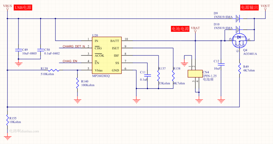
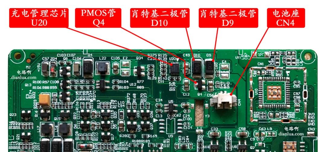
This is a mass-produced circuit, mature and stable. The physical circuit board is shown in the figure below, with several key components marked:
This article will explain the “automatic switching circuit between external USB power and built-in lithium battery power”, so we will hide irrelevant parts of the circuit mentioned above.
That is, hide the lithium battery charging management, power filtering, and other circuits:
After hiding, it looks like this:
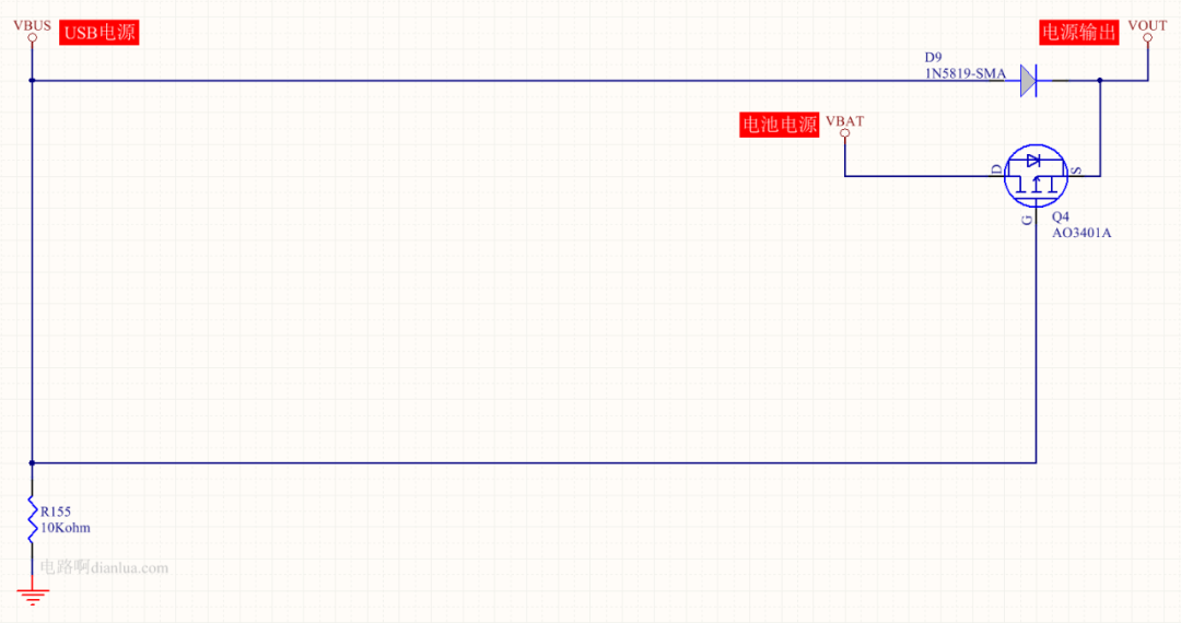
Now, the circuit becomes very simple; to achieve the power switching function, it only requires a diode, a MOSFET, and a resistor!
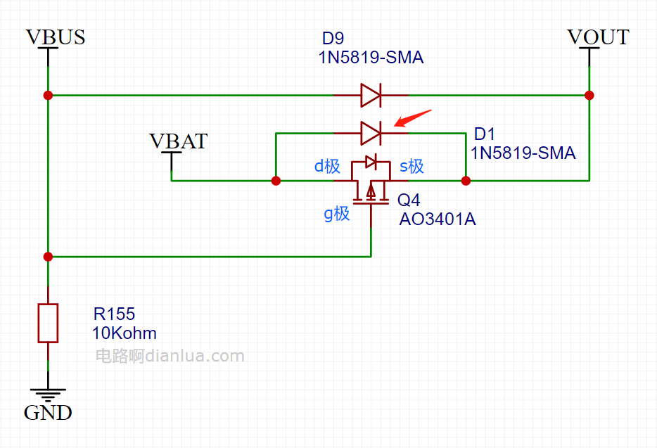
Let’s organize the “automatic switching circuit between external USB power and built-in lithium battery power” to make it look good:
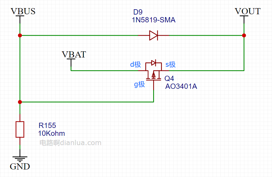
The functional logic is as follows:
-
1. When the USB power is connected, it is powered by the external USB source, that is, VBUS supplies power to VOUT.
-
2. When the USB power is disconnected, it switches to power from the built-in lithium battery, that is, VBAT supplies power to VOUT.
-
3. When the USB power is reconnected, it switches back to power from the external USB source, that is, VBUS supplies power to VOUT.
Assuming the voltage of VBUS is 5V and the voltage of VBAT is 3.7V, we will begin the analysis.
1. When the USB power is connected:
VBUS reaches VOUT through the Schottky diode D9.
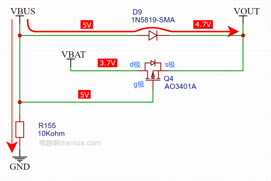
The forward voltage drop of the Schottky diode is about 0.3V, and the USB voltage VBUS = 5V, so:
Since VBAT is 3.7V, the source of the MOSFET Q4 is 4.7V, and the gate is 5V, thus:
Vgs = 5V – 4.7V = 0.3V > 0
So the MOSFET is in the off state, and its body diode is also reverse biased.
Due to the presence of resistor R155, some power loss occurs, and the current through R155 is:
2. When the USB power is disconnected:
The voltage of VBUS will start to drop from 5V, and resistor R155 will discharge VBUS.
The voltage of VBUS needs to drop quickly because if it drops slowly, it will cause the MOSFET Q4 to turn on slowly, making it unable to switch quickly to battery VBAT power.
As shown in the figure below, assuming VBUS slowly drops to 4.9V, that is, the gate of MOSFET Q4 is 4.9V. The battery voltage VBAT drops by about 0.7V through the body diode of MOSFET Q4, resulting in 3V, meaning the Vgs voltage of the MOSFET is:
The MOSFET still does not conduct, and the power supply to VOUT has not fully switched to VBAT.

Assuming VBUS has dropped to 1V, as shown in the figure below.
Then Vgs = 1V – 3V = -2V, and the MOSFET is gradually turning on.
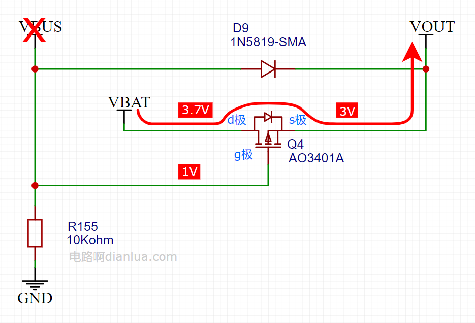
Eventually, VBUS will drop to 0V, and the MOSFET will be fully turned on, switching VOUT to be powered by VBAT, with VOUT voltage becoming 3.7V:

The filter capacitor connected to VBUS will cause its voltage to drop slowly. If it is found that the voltage of VBUS is dropping too slowly, the resistance of R155 can be reduced. However, this will increase the current through R155 when the USB power is inserted, increasing unnecessary power consumption.
Therefore, the resistance of R155 cannot be too large or too small; it must be determined based on the actual debugging effect.
3. When the USB power is reinserted:
As shown in the figure below, Vgs of MOSFET Q4 = 5V – 4.7V > 0, the MOSFET does not conduct, and its body diode is also reverse biased.
VOUT switches to be powered by VBUS, and the VOUT voltage becomes 4.7V.

3. Performance Improvement
At the moment when the USB power is unplugged, is it possible that the MOSFET Q4 does not turn on quickly enough, causing the voltage of VBAT to not switch over in time?
If the MOSFET Q4 does not turn on quickly, the VBAT power supply cannot be timely, which may cause VOUT voltage to drop too much, leading to abnormal operation of the VOUT load circuit. If the load of the circuit is heavy, drawing a large current, the problem of excessive voltage drop during power supply switching is particularly likely to occur.
-
1. The speed of the MOSFET turning on can be accelerated. This can be achieved by reducing the capacitance value of the filter capacitor connected to VBUS and reducing the resistance of R155, both of which allow VBUS to discharge quickly, thereby allowing Vgs to reach the voltage that fully turns on the MOSFET more quickly.
The forward voltage drop of this Schottky diode D1 is about 0.3V, which is smaller than that of the body diode of the MOSFET. Before the MOSFET is fully turned on, VBAT can supply power to VOUT through the Schottky diode D1, alleviating the problem of excessive voltage drop at VOUT.
This method is very practical, and this circuit and method have been applied for a utility model patent.In fact, many ordinary circuits have been applied for utility model patents, even though these circuits have been used by the public for a long time; I won’t elaborate on this here.
In addition to the aforementioned eBook reader, many products use this switching circuit.
For example, the well-known company 01Studio in the MicroPython field has several development boards that feature this switching circuit.
Taking one of the models, the “pyWiFi-ESP32” development board, as an example, its power section circuit diagram is as follows:
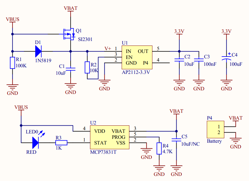
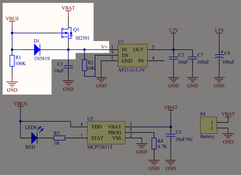
The relevant power switching circuit is shown here:
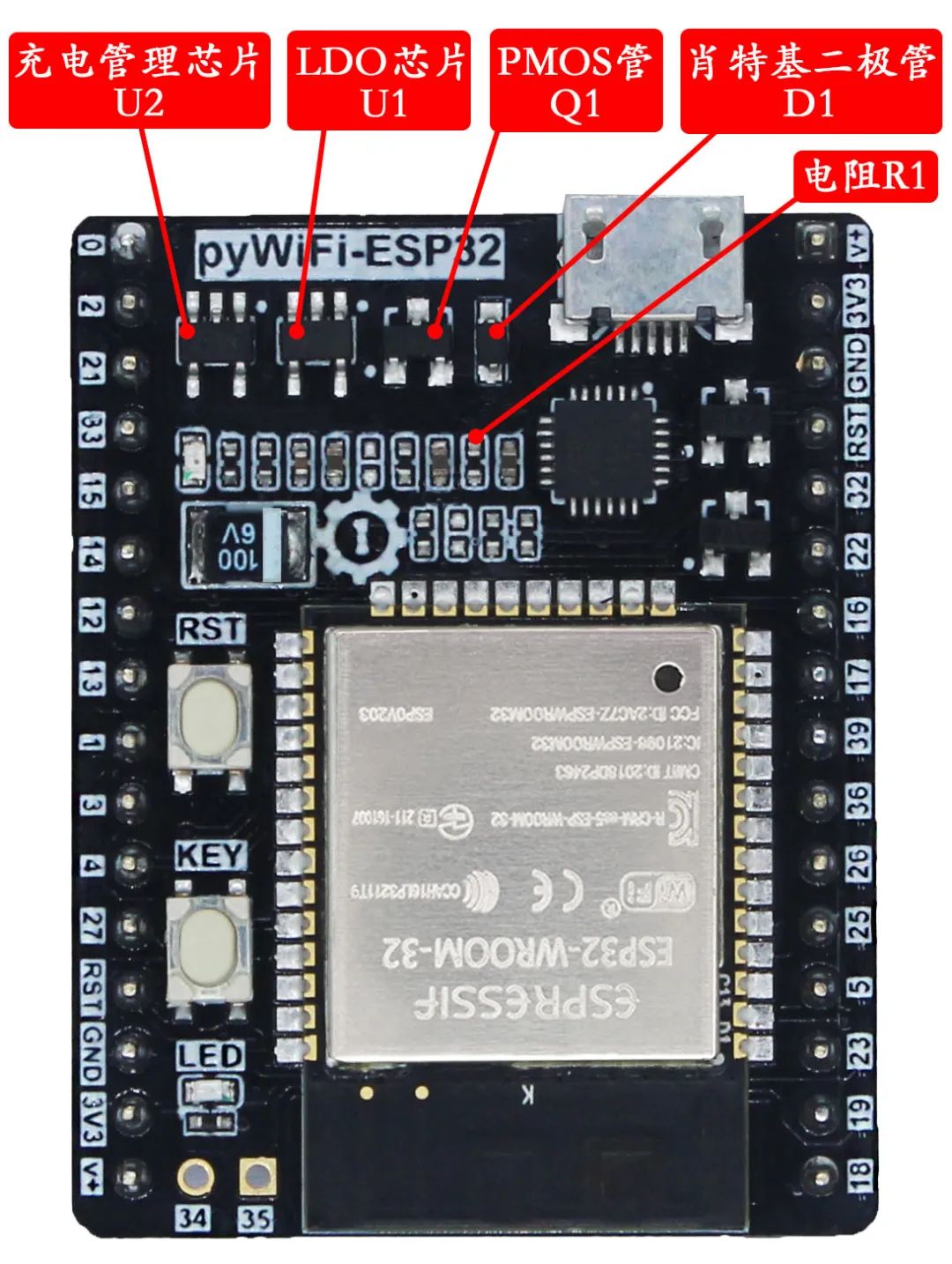
Annotated corresponding physical image:
This article is probably the most “verbose” piece discussing this circuit on the internet so far. I wonder if it might be too “dry” and hard to digest.
On the 6th, the State Taxation Administration announced a notice to launch and optimize 28 measures in five aspects to facilitate tax payment, focusing on supporting a large number of small and micro enterprises and individual businesses led by private enterprises.
On the 6th, the State Taxation Administration announced a notice to launch and optimize 28 measures in five aspects to facilitate tax payment, focusing on supporting a large number of small and micro enterprises and individual businesses led by private enterprises.
On the 6th, the State Taxation Administration announced a notice to launch and optimize 28 measures in five aspects to facilitate tax payment, focusing on supporting a large number of small and micro enterprises and individual businesses led by private enterprises.
-
National Big Fund Reduces Holdings of China Electric Port Shares
-
After the Festival, A-shares Semiconductor Sector Rises, with Several Companies Rising Nearly 30%
-
Japan’s Chip Disaster
-
Industry Secret: Chip Counterfeiting Technology, You Don’t Know the Inside Story!
-
Intel’s Path to Redemption
-
First Test on the Internet! High-Performance Domestic General Dual-Core Bluetooth MCU Experience!
-
Great Wall Motors Wei Jianjun: Chinese Electric Vehicles Lack Core Technology
-
Will 2024 Be the Year of Advanced Packaging?
-
Awesome! Yiwu Small Speaker, Powerful Functionality in a Tiny Circuit Board
-
It Smoked Again! Which DCDC Power Chip is the Real One?