Application of Multi-Node RS-485 Bus Protection Circuit in New Energy Field

Application of Multi-Node RS-485 Bus Protection Circuit in New Energy Field

With the popularization of the concept of “carbon neutrality”, industries such as photovoltaics, wind power, and energy storage are once again ushering in a boom. As a commonly used communication interface in these industries, RS-485 often requires additional protection circuits to ensure stable communication. This article will introduce a protection circuit scheme for multi-node environments.

“Carbon neutrality” is a hot topic this year, and one of the key elements to achieving “carbon neutrality” is the vigorous development of new energy. In the future, many sub-industries within new energy will make outstanding contributions to “carbon neutrality” in the construction of ecological civilization in our country. For example, a series of industries such as photovoltaic power generation, wind power generation, and inverter energy storage will see vigorous growth.

As a commonly used interface for communication between devices in the new energy field, the RS-485 bus often needs to add peripheral protection circuits to withstand the effects of high-level static electricity or surges, ensuring its communication stability. However, engineers usually use gas discharge tubes and TVS diodes to build protective circuits. The junction capacitance of this circuit is relatively high, which can affect bus communication when there are many nodes. To address this issue, this article will introduce a reference design scheme for low-junction-capacitance peripheral circuits.

This article will focus on the bus protection circuit schemes related to RS-485.
Application of Multi-Node RS-485 Bus Protection Circuit in New Energy Field Commonly Used RS-485 Protection Circuits

Application of Multi-Node RS-485 Bus Protection Circuit in New Energy Field

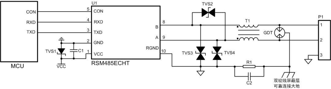
Figure 1 Protection Circuit 1

As shown in Figure 1, the gas discharge tube releases most of the surge current at the interface, while the common-mode inductor filters out common-mode signal interference, and the TVS further reduces the residual voltage after the gas discharge tube, thus protecting the subsequent circuit. The RSM485ECHT module, using the protection circuit shown in Figure 1, can withstand contact static electricity of ±8kV, common-mode surge of ±4kV, and differential-mode surge of ±2kV, meeting the requirements of most industrial sites for RS-485 node static and surge levels.

Although the protection circuit shown in Figure 1 has strong protective capabilities, its junction capacitance is relatively large. The junction capacitance of A-RGND or B-RGND is about 2.5nF. When there are many nodes on the bus using the protection circuit in Figure 1, the bus capacitance becomes large, causing signal reflections and flattening of the signal edges, which deteriorates signal quality and may even lead to communication anomalies.

Application of Multi-Node RS-485 Bus Protection Circuit in New Energy Field Signal Reflection Issues Caused by Bus Capacitance

When the signal is transmitted on the communication line and reaches the protection circuit at the RS-485 node, the junction capacitance of the protection circuit changes the instantaneous impedance of the signal, causing part of the signal to be reflected while another part is distorted and continues to propagate.

Figure 2 shows the differential waveform of a single node RSM485ECHT sending; Figure 3 shows a schematic diagram of RS-485 bus connecting six protection circuits, with a distance of about 30cm between each node, using twisted pair connections. Figures 4 and 5 show the waveform test points 1 and 6 (marked positions in Figure 3) with six circuits as shown in Figure 1 connected to the bus. The rise/fall times of the waveforms are prolonged, and the waveform at test point 1 has become step-shaped.

Application of Multi-Node RS-485 Bus Protection Circuit in New Energy Field

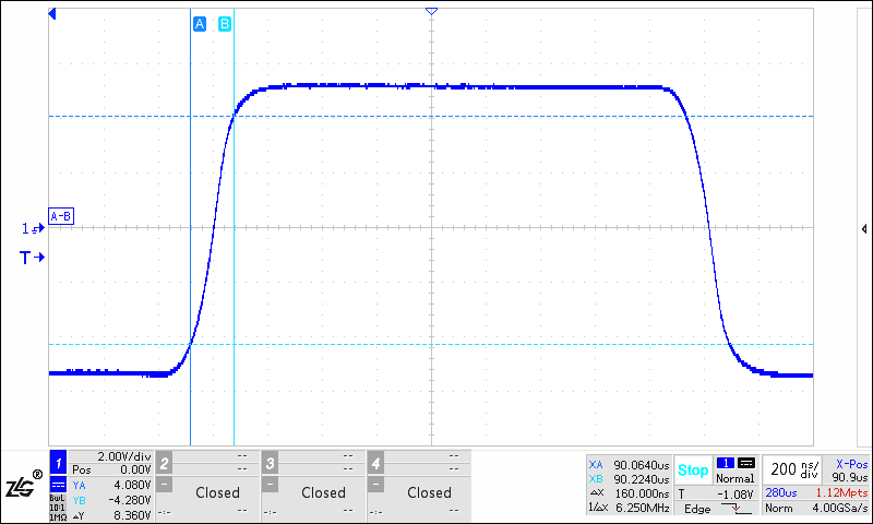
Figure 2 Differential Waveform of RSM485ECHT Single Node RS-485 Interface

Application of Multi-Node RS-485 Bus Protection Circuit in New Energy Field

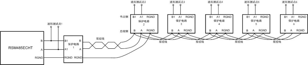
Figure 3 Schematic Diagram of Bus Connecting Six Protection Circuits

Application of Multi-Node RS-485 Bus Protection Circuit in New Energy Field

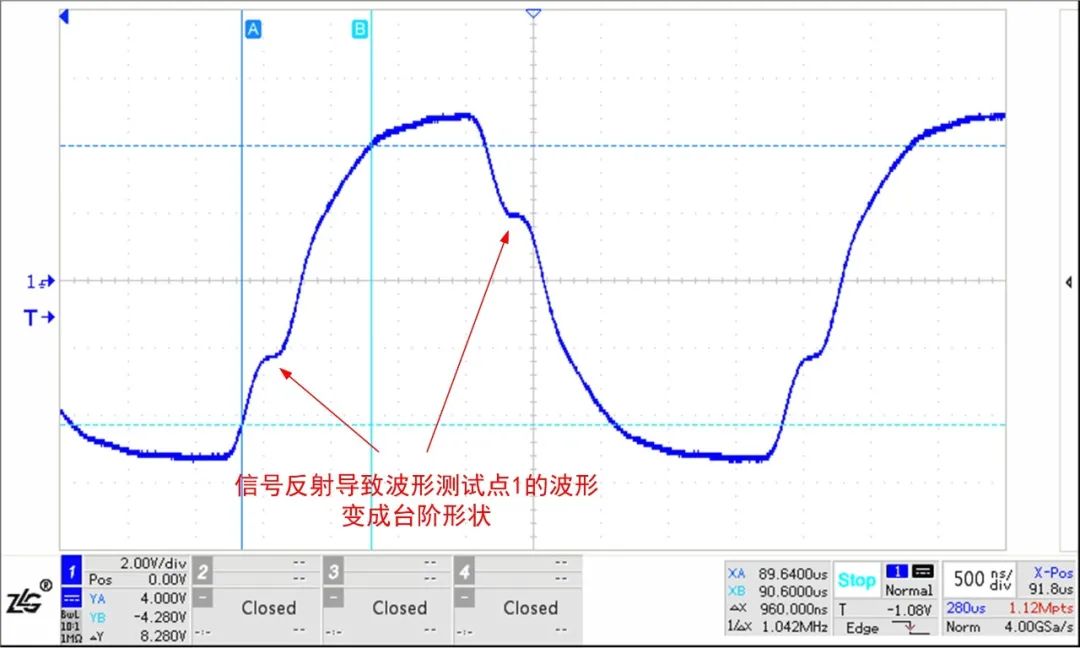
Figure 4 Waveform Test Point 1 of RSM485ECHT with Six Protection Circuits

Application of Multi-Node RS-485 Bus Protection Circuit in New Energy Field

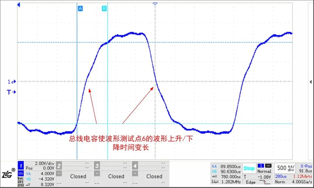
Figure 5 Waveform Test Point 6 of RSM485ECHT with Six Protection Circuits

The RS-485 interface of RSM485ECHT has strong driving capability. Below are the test waveforms of commonly used RS-485 transceiver chips on the market under the same test conditions. It can be seen that the waveforms have been severely disturbed, and the reflected waveforms have reached near the threshold level of the RS-485 chip, which may cause communication anomalies. Therefore, in practical applications, a transceiver with strong driving capability should be selected.

Application of Multi-Node RS-485 Bus Protection Circuit in New Energy Field

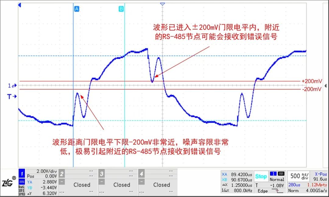
Figure 6 Waveform Test Point 1 of a Certain RS-485 Transceiver with Six Protection Circuits

Application of Multi-Node RS-485 Bus Protection Circuit in New Energy Field Low Junction Capacitance Protection Circuit

When the number of communication nodes is large, a protection circuit like the one shown in Figure 8 can be used, where the junction capacitance of A-RGND or B-RGND is only 20pF. Although the junction capacitance of the TVS is relatively large, the junction capacitance of ordinary diodes is very small. The junction capacitance of the TVS and ordinary diodes is in series, thus reducing the junction capacitance of the protection circuit. Using Figure 8 for networking as shown in Figure 3, the waveform at test point 1 is shown in Figure 9, and the waveform at test point 6 is shown in Figure 10, where the waveforms have basically not changed.

Application of Multi-Node RS-485 Bus Protection Circuit in New Energy Field

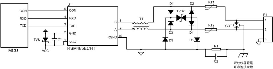
Figure 8 Protection Circuit 2 (Low Junction Capacitance)

Application of Multi-Node RS-485 Bus Protection Circuit in New Energy Field

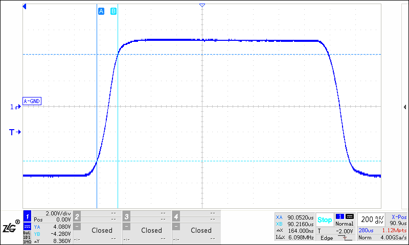
Figure 9 Waveform Test Point 1 of RSM485ECHT with Six Protection Circuits 2

Application of Multi-Node RS-485 Bus Protection Circuit in New Energy Field

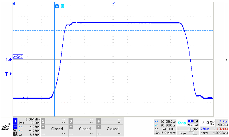
Figure 10 Waveform Test Point 6 of RSM485ECHT with Six Protection Circuits 2

Application of Multi-Node RS-485 Bus Protection Circuit in New Energy Field Conclusion

The protection circuits mounted on the bus will change the instantaneous impedance of the signal, leading to signal reflections. When there are many nodes on the bus, the bus capacitance becomes large, which interferes with the bus waveform and affects the quality of the communication signal. Therefore, to reduce the impact of the protection circuit on bus communication in practical applications, a transceiver with strong driving capability should be selected. Additionally, if the protection circuit uses the circuit shown in Figure 1, a low junction capacitance TVS should be selected, or a low junction capacitance protection circuit like the one shown in Figure 8 can be used.

As a leading brand in bus isolation in China, ZLG Zhiyuan Electronics has launched the RSM series isolated transceivers for the new energy and industrial fields after twenty years of technical accumulation. The RSM series products effectively solve problems such as bus interference and communication anomalies. Compared with traditional designs, the RSM series products have a complete built-in isolation DC-DC circuit, signal isolation circuit, RS-485 bus transceiver circuit, and bus protection circuit, featuring high integration and reliability, effectively helping users improve the bus communication protection level.
Application of Multi-Node RS-485 Bus Protection Circuit in New Energy Field
  • Supported baud rates: 500Kbps, 115.2Kbps, 9.6Kbps, etc.;

  • Node count: 256, 128, 32, etc.;

  • Channel count: single, dual, quad, etc.;

  • Operating temperature: -40~85℃ or -40~105℃;

  • Isolation voltage: 2500VDC or 3500VDC;

  • Miniature or standard modular packaging;

  • Enclosure and potting materials meet UL94 V-0 standards;

  • Low electromagnetic radiation and high electromagnetic interference resistance.

Application of Multi-Node RS-485 Bus Protection Circuit in New Energy Field

ZLG Zhiyuan Electronics Official New Media Platform

Application of Multi-Node RS-485 Bus Protection Circuit in New Energy Field

Leave a Comment