Have engineers encountered situations where testing a single RS-485 device shows no abnormalities, but communication data anomalies or connection failures occur when the device is networked? What are the reasons for these errors? This article will reveal the abnormality of RS-485 networking from the perspective of threshold levels.
The RS-485 bus is widely used in industrial communication, power monitoring, and instrumentation due to its simple structure, long communication distance, high communication speed, and low cost.If terminal resistors are connected to the bus, the RS-485 differential voltage between A and B may fall within the threshold level (±200mV) when the bus is idle, which may lead to communication errors. So, what causes these errors?What changes occur to the data received by the MCU?
 Reasons for Data Errors
As shown in Figure 1, this is the UART timing diagram with 8 data bits and no parity bit. When using UART for communication, the MCU begins receiving subsequent data after detecting the start bit.
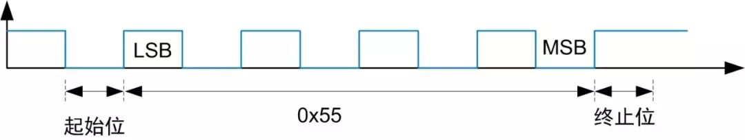
Figure 1 No Parity Bit, 8 Data Bits, Serial Timing Diagram
As shown in Figure 2, this illustrates the condition under which the STM32 serial peripheral detects the start bit. When a falling edge (3 high levels + 1 low level) is detected and both sampling sequences 1 and 2 are 0, the STM32 identifies a start bit.
Each bit is sampled 16 times, with the sampling interval being tbit/16, where tbit is the time for each bit. For example, at a communication baud rate of 115.2kbps, tbit=1/115.2k=8.68us, making the sampling interval 8.68us/16=0.5425us.
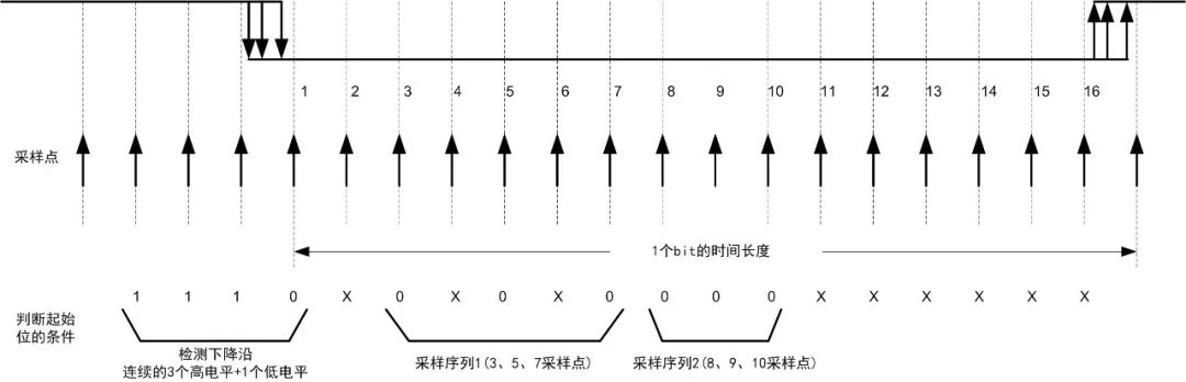
Figure 2 Conditions for STM32 Serial Peripheral to Detect Start Bit
Next, taking the threshold level of RSM485PCHT as an example, when the AB differential voltage is within ±200mV, the RXD pin of the module outputs an uncertain state.
When the bus becomes idle, if the RXD pin outputs a low level, it may lead to the MCU receiving erroneous data or mistakenly receiving a 0x00 after valid data.
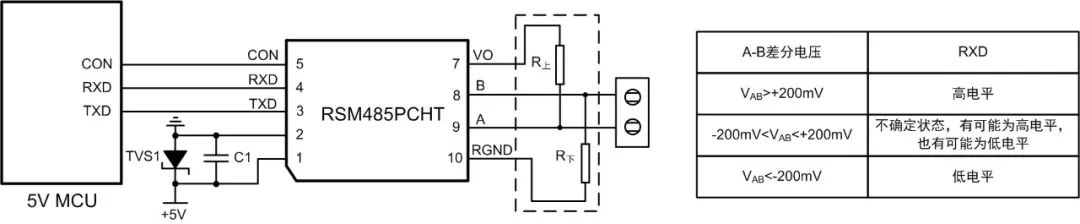
Figure 3 RSM485PCHT Threshold Level
 What Changes Occur to the Data?
As shown in Figure 4, when the AB differential voltage is within ±200mV threshold level, Transceiver 1 outputs a high level, while Transceiver 2 outputs a low level, indicating that Transceiver 2 may cause the MCU to receive erroneous data and mistakenly receive a 0x00 after the data.
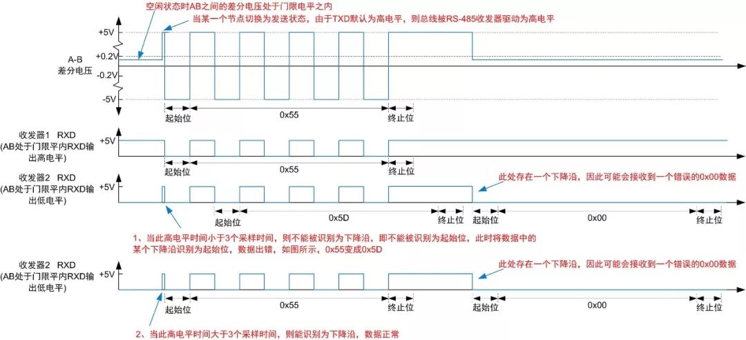
Figure 4 Extra 0x00 After Data
As shown in Figure 5, if there is a continuous data signal on the bus or multiple bytes of data are continuously sent, the idle state between the data may be recognized as a start bit by Transceiver 2, leading to continuous data errors.
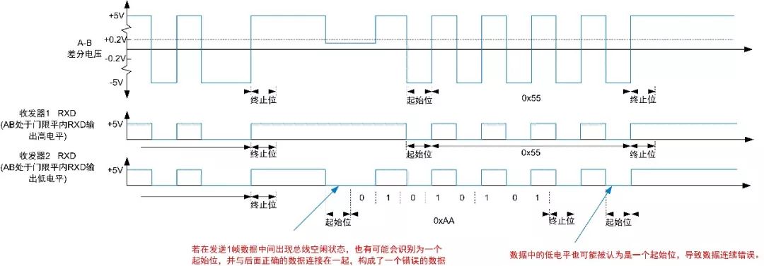
Figure 5 Continuous Data Errors
 Solutions
If the AB differential voltage is within the threshold level when the bus is idle, it may lead to data errors. The following methods can be used to avoid the AB differential voltage being within the threshold level when the bus is idle.
Solution 1:If the networking distance is short and there are no reflection issues or minimal reflections, terminal resistors can be omitted to enhance the bus signal amplitude. The specific amplitude changes are shown in Figure 6.
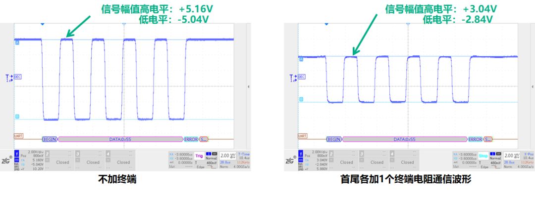
Figure 6 Impact of Terminal Resistor on Bus Level
Solution 2:If the networking distance is longer and reflection issues currently exist on the bus signal, terminal resistors should be added to resolve the reflection issue. For such applications, the ZhiYuan Electronics RSM(3)485PCHT module can be used. During RS-485 interface design, a small-value pull-up and pull-down resistor can be externally added to adjust the voltage value during idle state, ensuring it is outside the threshold level. The specific amplitude changes are shown in Figure 7.
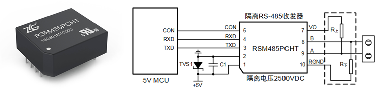
Figure 7 RSM(3)485PCHT Physical and Application Connection Diagram
Solution 3:If the networking distance is longer and reflection issues currently exist on the bus signal, terminal resistors should be added to solve the reflection issue. For such applications, the ZhiYuan Electronics RSM(3)485ECHT module can also be used. The RSM(3)485ECHT has a very high bus compatibility with a threshold level of -40mV to -20mV, as shown in Figure 8. Even when the bus level is pulled down by terminal resistors (in the worst-case scenario, the bus high level amplitude is 0V), the bus level can still be recognized, ensuring communication stability.
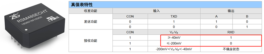
Figure 8 RSM(3)485ECHT Physical and Threshold Level Parameters

 If you have any questions, you can:
 Add WeChat of Xiao Z: zlgmcu-888
 Call ZLG ZhiYuan Electronics official technical hotline: 400-888-4005.