 CAN Communication
The CAN protocol, after being standardized by ISO, is divided into two categories based on transmission speed: ISO11898-2 (high-speed) and ISO11898-3 (low-speed). Implementing CAN communication requires a CAN controller and a CAN transceiver. Currently, there are two mainstream solutions on the market:
-
Integrating the MCU and CAN controller together, with an external CAN transceiver; -
Using external forms for both the CAN controller and the CAN transceiver, as shown in Block Diagrams 1 and 2.
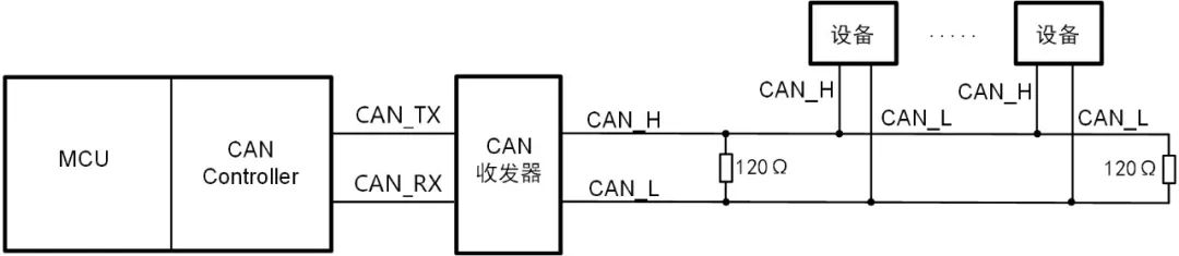
Figure 1: CAN controller integrated with MCU
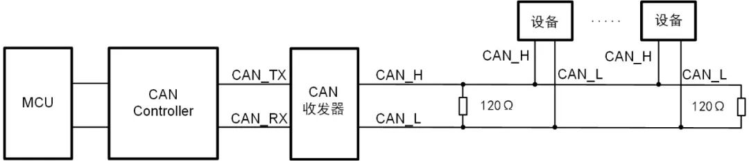
Figure 2: External configuration for CAN controller and transceiver
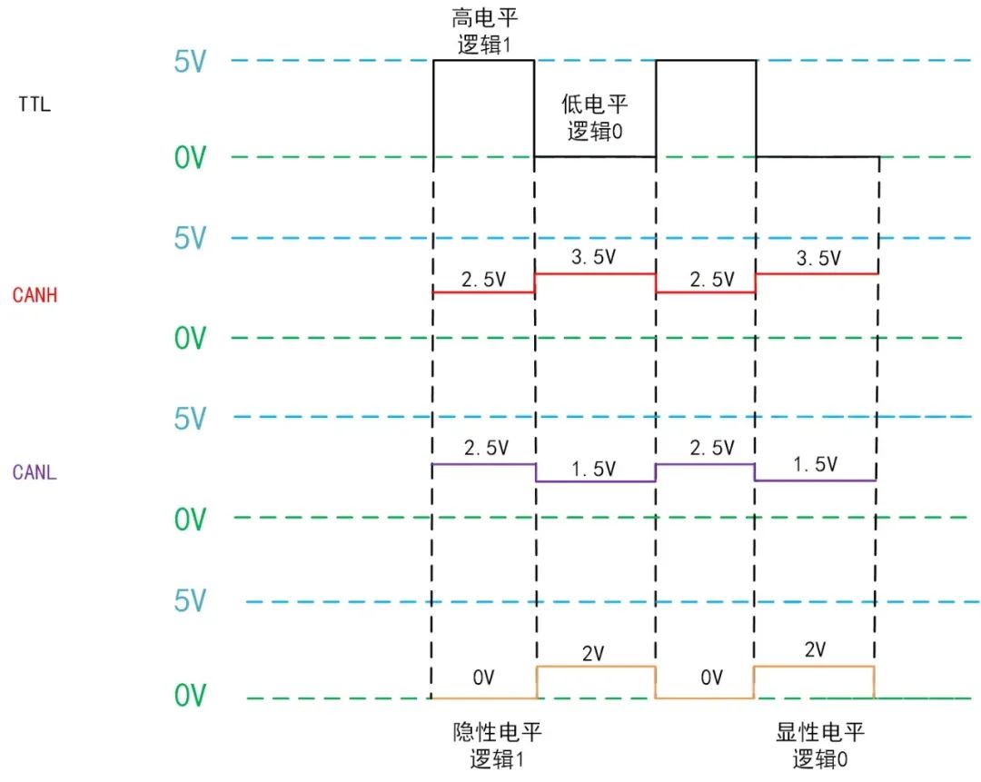
CAN data transmission is achieved through the voltage difference between two wires (differential transmission), which are referred to as CANH and CANL. According to standard definitions,CANH=CANL=2.5V (CANH-CANL=0V) represents a dominant level, or “logic 1”; CANH=3.5V, CANL=1.5V (CANH-CANL=2V) represents a recessive level, or “logic 0”, as shown in Figure 3. (The dominant level has higher priority than the recessive level, which is particularly evident in multi-master arbitration on the CAN bus.)
 RS-485 Communication
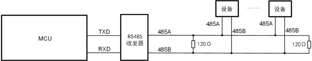
Figure 4: RS-485 working block diagram
-
When RS-485 acts as a driver,V485A-V485B=+(2~6)V represents a high level, logic 1; V485A-V485B=-(2~6)V represents a low level, logic 0;
-
When RS-485 acts as a receiver,V485A-V485B≥+200mV represents a high level, logic 1; V485A-V485B≤-200mV represents a low level, logic 0.
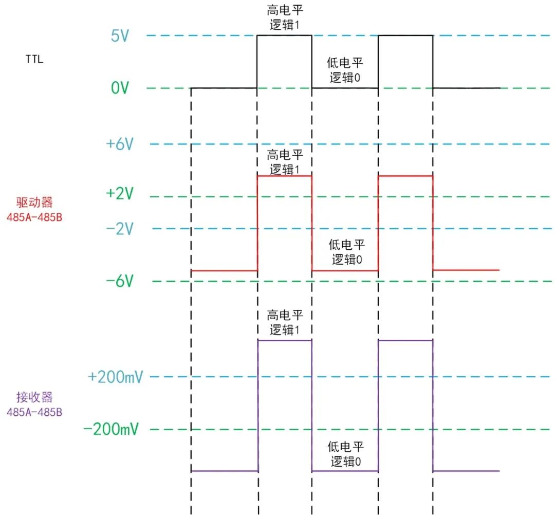
Figure 5: Standard definition of RS-485 levels
The input impedance of the transceiver, unit load, and the number of nodes are closely related, as shown in Table 1. The RS-485 bus also requires pull-up and pull-down resistors (with 485A connected to pull-up and 485B connected to pull-down), with the purpose of:
-
Avoiding the differential voltage between 485A and 485B being in the range of -200mV~+200mV (the bus is in an uncertain state); -
Avoiding the bus outputting a low level (the UART protocol start bit is low, leading to communication anomalies); -
Avoiding electromagnetic interference issues on the bus.
Table 1: Relationship between receiver input impedance, unit load, and number of nodes
|
Unit Load |
Number of Nodes (pieces) |
Receiver Input Impedance (kΩ) |
|
1 |
32 |
12 |
|
1/2 |
64 |
24 |
|
1/4 |
128 |
48 |
|
1/8 |
256 |
96 |
 Industry Applications
CAN is a serial communication protocol characterized by high reliability, high real-time performance, and high flexibility. It supports high-security distributed real-time control scenarios, mainly applied in high-speed data transmission and real-time control systems. For example, CAN is used in smart factory applications as shown in Figure 6, connecting the USBCAN-4E-U communication box with a PC monitoring machine, which is then connected to the factory’s CAN bus. Each workstation on the production line feeds back monitoring data to the PC monitoring machine via the CAN bus, allowing monitoring personnel to monitor each workstation in real-time and effectively prevent production accidents. If adjacent workstations on a production line are far apart (distance >200m), it is recommended to add a CANFDBridge to the CAN bus to ensure sufficient communication distance and achieve network extension functionality.
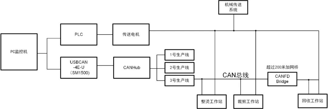
Figure 6: Application example of CAN bus in smart factories
Our company has launched the fully isolated CAN transceiver chip SM1500, packaged in DFN, with a size of only 12.45mm*9.85mm*3.00mm, capable of operating normally in environments ranging from -40° to +125°, suitable for automotive electronics, BMS, charging piles, petrochemical, and power monitoring fields.
RS-485 is a serial communication protocol characterized by good noise immunity, long data transmission distance, and a high number of device nodes, making it suitable for long-distance low-speed data transmission scenarios. For example, RS-485 is used in traffic light fault detection applications as shown in Figure 7, where ZLG provides main control, wireless communication, and communication interface protection product solutions for traffic light fault detection applications. The M6Y2C core board has rich peripheral interface resources, allowing connections with various sensors and monitoring devices, facilitating data collection and analysis by staff, accurately locating fault areas, and resolving issues.
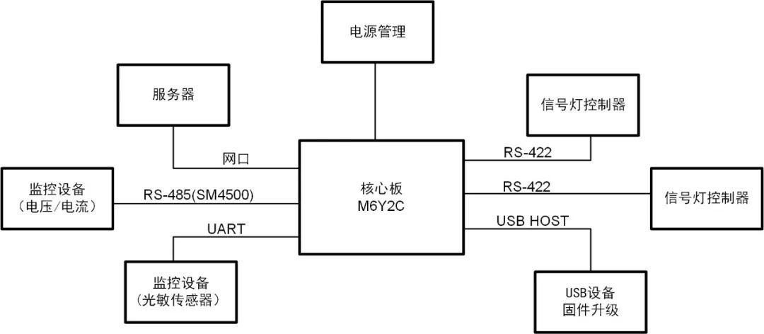
Figure 7: Application example of RS-485 bus in traffic light fault detection
Our company has launched the fully isolated RS-485 transceiver chip SM4500, packaged in DFN, with a size of only 12.45mm*9.85mm*3.00mm, capable of operating normally in environments ranging from -40° to +125°, suitable for petrochemical, power monitoring, rail transit, and stage lighting fields.
For more past articles, please click “Read the original text“.