Introduction
To save MCU I/O resources, RS-485 automatic transceivers are often used, but these types of transceivers encounter some application problems to varying degrees. How can these issues be resolved? This article will reveal the answers from the working principle.
 Introduction to Automatic Transceiver Circuits and Application Analysis
The common RS-485 automatic transceiver circuit is shown in Figure 1, and the circuit’s logic truth table is shown in Table 1.
-
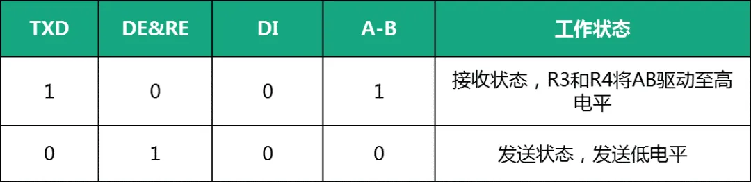
When TXD is low, DE and RE are high, and the RS-485 transceiver is in sending state, AB is low, meaning it sends a low signal to other nodes; -
When TXD changes from low to high, DE and RE become low, putting the RS-485 transceiver in receiving state. At this time, the AB pins are in high impedance state, R3 pulls pin B to GND, and R4 pulls pin A to VCC, making AB high, which sends a high signal to other nodes.
Since TXD is high, the RS-485 transceiver is in receiving state, so TXD only needs to remain high to receive data, meaning the automatic transceiver circuit is in receiving state while sending a high signal.
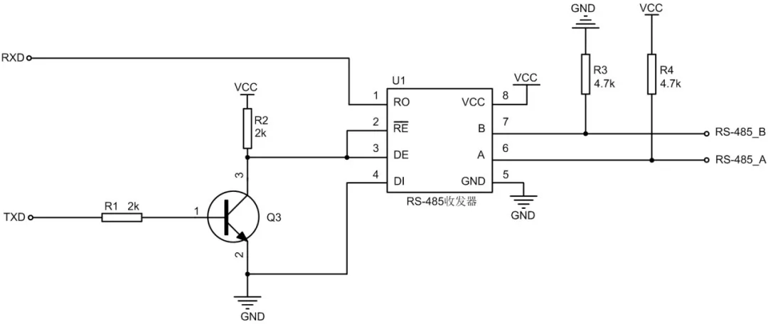
Figure 1 RS-485 Automatic Transceiver Schematic
 Common Application Problems and Solutions for Automatic Transceiver Circuits
The main reasons for the slow communication speed of RS-485 automatic transceivers are two:
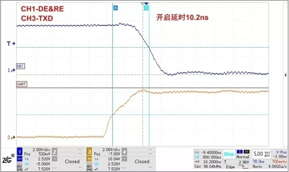
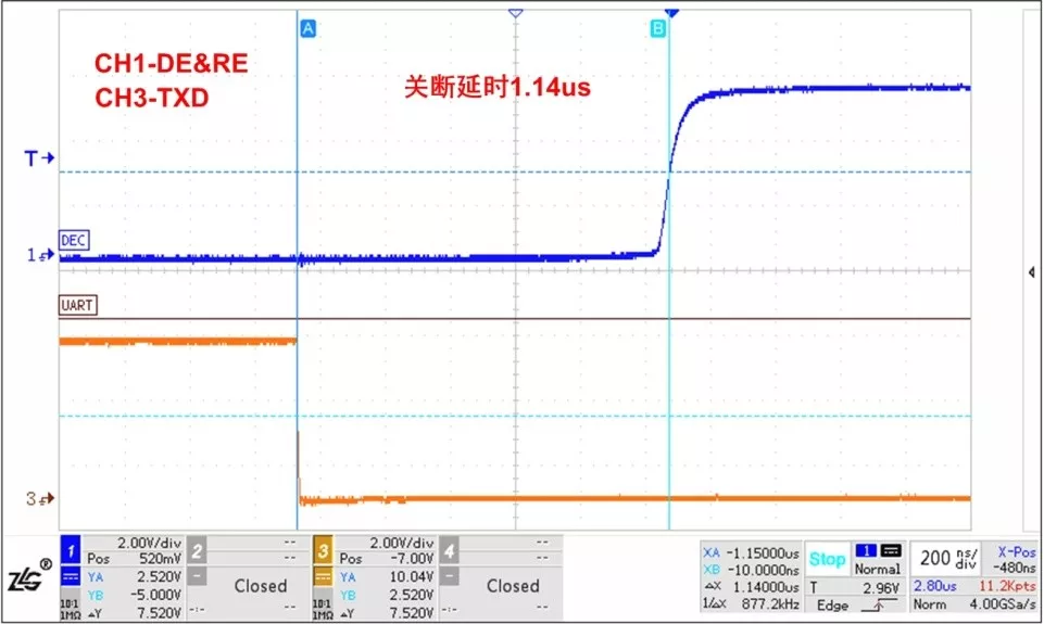
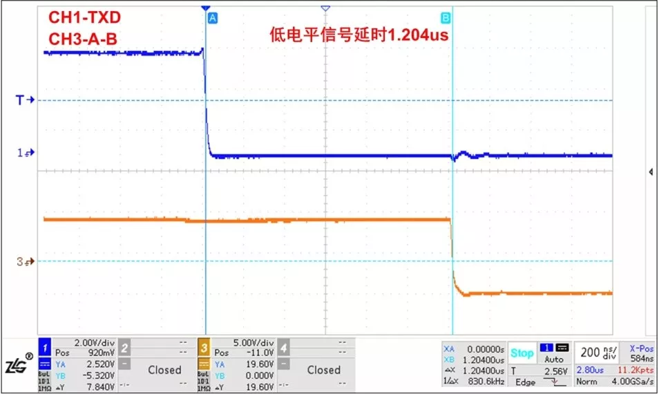
1.1 If using the automatic transceiver circuit shown in Figure 1, the turn-off time of the transistor is relatively long (mainly due to the storage time during the turn-off of the transistor). The turn-on delay time of the transistor in the inverse circuit shown in Figure 1 is 10.2ns, while the turn-off delay time is 1.14μs. Therefore, if TXD sends a low signal, the DE&RE pins will take a long time to rise to high, and the delay time for sending low signals will be long. The delay time for sending low signals in the circuit shown in Figure 1 is 1.468μs.
2. Risk of Communication Abnormalities at High Baud Rates
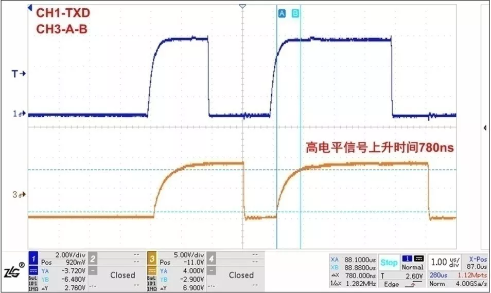
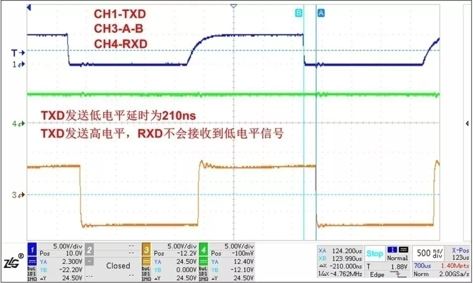
As shown in Figure 6, when TXD becomes high, DE&RE pins drop to low, and the AB differential voltage rises slowly. Since the RS-485 transceiver is in receiving state at this time, before the AB differential voltage rises to the RS-485 transceiver threshold level, the RXD pin will show a low signal for a period of time. For example, for a transceiver with a threshold level of -200mV~-50mV, the RS-485 transceiver can output a low signal until the AB differential voltage rises to -50mV. The duration of this low signal is related to the rising time of the AB differential voltage and the receiving delay of the RS-485 transceiver.
Since the serial port typically divides each bit into 16 parts and detects the level signal of the middle 3 parts to determine the signal high or low, if this low signal persists during the signal detection of each bit, it will cause the MCU to receive a start bit, thus receiving incorrect data. Therefore, this problem also limits the application of high-speed communication and reduces communication reliability.
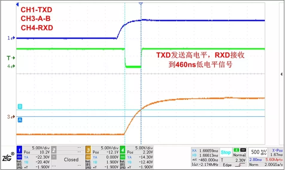
Figure 6 TXD Sends High Signal, RXD Receives a Low Signal
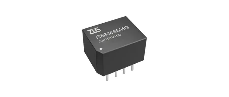
Isolated RS-485 Transceiver RSM485MG
• Mini size or standard modular packaging
• Low electromagnetic radiation and high resistance to electromagnetic interference
• Effectively enhances the bus communication protection level
Reference Price: 29 Yuan

Click to Buy
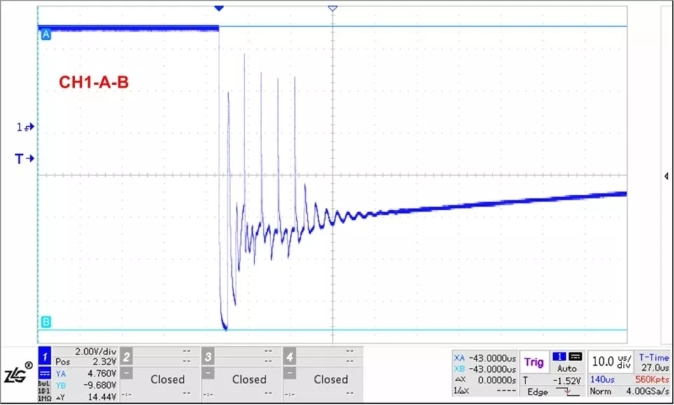
In high electrostatic or surge environments, it is necessary to add peripheral protection circuits to protect the RS-485 transceiver. If the junction capacitance of the protection circuit added to the RS-485 bus is large, it will affect the quality of the communication waveform and may even lead to communication abnormalities. The communication waveform using high junction capacitance protection circuits is shown in Figure 8, with severe distortion affecting communication quality.
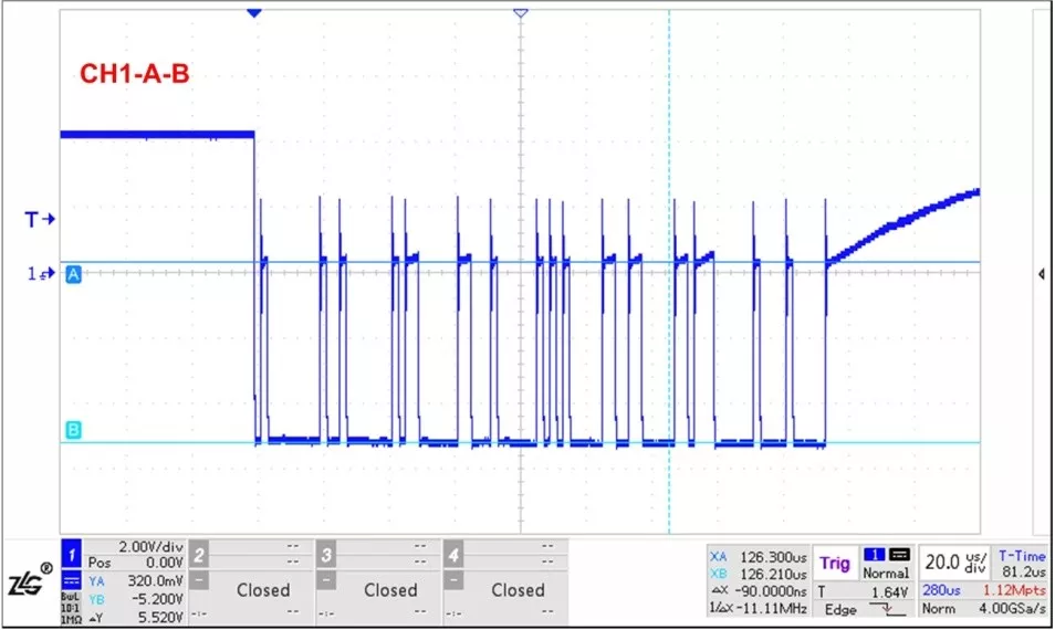
Figure 8 Waveform Affected by High Junction Capacitance
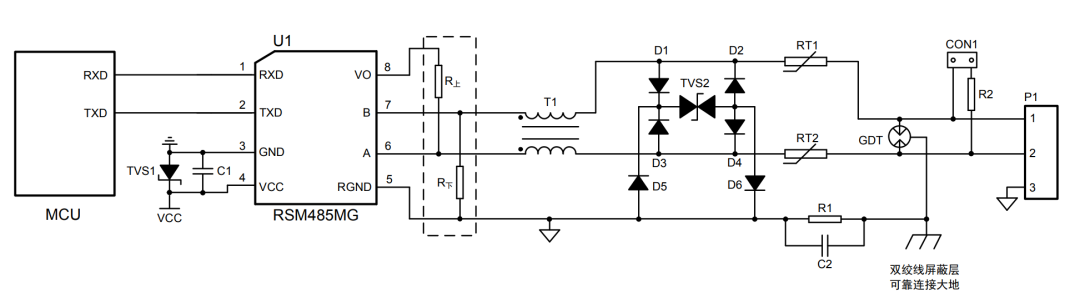
Figure 9 Low Junction Capacitance Protection Circuit
When the automatic transceiver circuit sends a high signal, it is always driven by pull-up and pull-down resistors for a period of time or the entire time. To improve the driving capability of sending high signals, it is necessary to use pull-up and pull-down resistors with a smaller resistance value. Due to the driving capability limitations of the RS-485 transceiver itself, the pull-up and pull-down resistors cannot be chosen too small. Generally, the parallel value of all pull-up and pull-down resistors on the bus cannot be less than 375 ohms; thus, the driving capability of sending high signals in the automatic transceiver circuit is very limited. After adding terminal resistors to the RS-485 bus, the AB differential voltage for sending high signals is obtained from the voltage division of the terminal resistors and pull-up/pull-down resistors, resulting in a low amplitude for the high signal sent. Therefore, when using automatic transceiver RS-485 transceivers, it is advisable not to use terminal resistors.
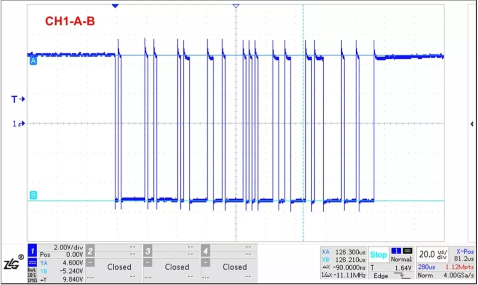
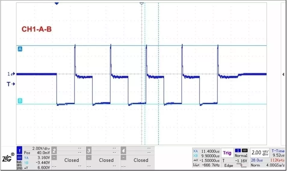
Due to the limited driving capability of the automatic transceiver circuit, the communication distance it can achieve is also restricted. The communication waveforms for twisted pairs of lengths 8m and 200m are shown in Figures 11 and 12. The communication waveform is good and communication is normal at a distance of 8m, while at 200m, normal communication is no longer possible.Therefore, for longer communication distances, pull-up and pull-down resistors and terminal resistors can be added externally to the automatic transceiver RS-485 transceiver to improve the communication waveform. The improved communication waveform after adding them is shown in Figure 13, where the waveform has significantly improved and normal communication is possible, but the amplitude of the high signal sent remains low.
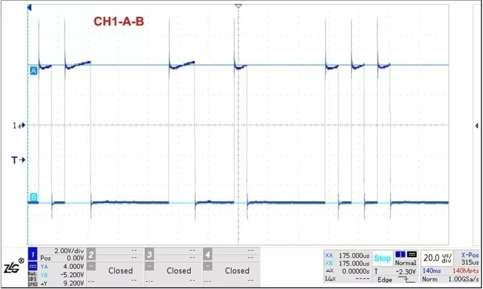
Figure 11 Communication Waveform Through 8m Twisted Pair
If there are high requirements for communication distance, it is not recommended to use automatic transceiver modules. Instead, you can choose ZLG Zhiyuan Electronics’ isolated RS-485 transceivers with transceiver control functions, RSM485ECHT or RSM3485ECHT, which can achieve communication distances of up to 1200m.With a communication speed of 500kbps and a communication distance of 1200m, the communication waveform with terminal resistors of 120 ohms at both ends of the bus is shown in Figure 14, where the amplitude of the signal sent by RSM485ECHT can reach 2.6V, greatly enhancing communication reliability.
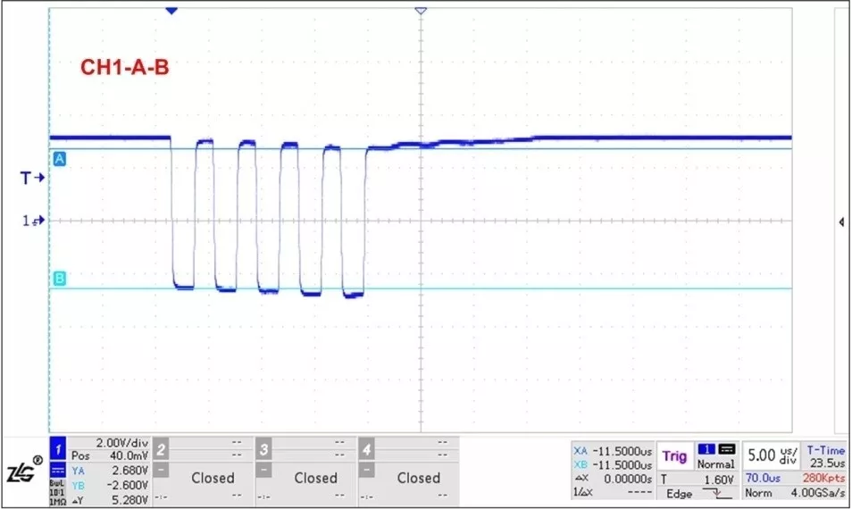
Figure 14 Communication Distance of 1200m, Terminal Resistors Added at Both Ends, RSM485ECHT Sending Waveform
 Conclusion
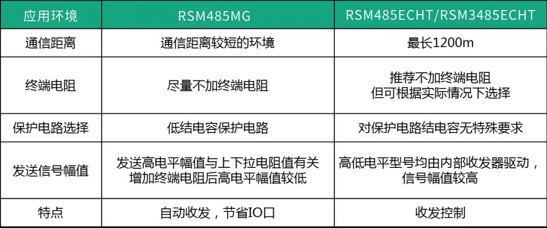
Table 2 Product Recommendation Application Situation Description
Isolated CAN Transceiver RSM3485ECHT
• 3.15~3.45VDC
• High-speed type
• 24mA Static Current
Reference Price: 29 Yuan
Click to Buy