
The RS-485 bus is widely used in industrial environments, which may experience high levels of electrostatic or surge interference. Engineers typically use gas discharge tubes and TVS diodes to build protective circuits. However, these circuits have a high junction capacitance, which, if improperly applied, can affect communication. This article will introduce a low junction capacitance peripheral circuit.
1
Common RS-485 Protective Circuits
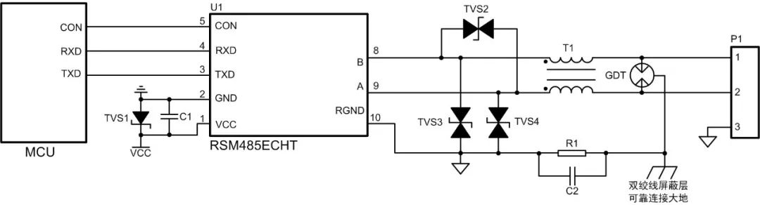
Figure 1 Protective Circuit 1
As shown in Figure 1, the gas discharge tube releases most of the surge current at the interface, while the common mode inductor filters out common mode signal interference. The TVS further reduces the residual voltage after the gas discharge tube, thereby protecting the subsequent circuit.The RSM485ECHT module with the protective circuit shown in Figure 1 can withstand contact electrostatic discharge of ±8kV, common mode surge of ±4kV, and differential mode surge of ±2kV, meeting the requirements for RS-485 node electrostatic and surge levels in most industrial sites.
Although the protective circuit shown in Figure 1 has strong protection capabilities, it has a large junction capacitance. The junction capacitance of A-RGND or B-RGND is about 2.5nF. When there are many nodes on the bus all using the protective circuit in Figure 1, the bus capacitance becomes large, resulting in signal reflection and a slower signal edge, which degrades signal quality and may even lead to communication anomalies.
2
Signal Reflection Issues Caused by Bus Capacitance
When the signal is transmitted along the communication line and reaches the protective circuit at the RS-485 node, the junction capacitance of the protective circuit causes a change in the instantaneous impedance experienced by the signal. Part of the signal will be reflected, while another part will be distorted and continue propagating.
Figure 2 shows the differential waveform of a single RSM485ECHT node, while Figure 3 illustrates the schematic of the RS-485 bus connected to six protective circuits, with a distance of about 30cm between each node, connected using twisted pair cables. Figures 4 and 5 show the waveform test points 1 and 6 (marked positions in Figure 3) for the bus connected to six circuits of Figure 1. The rise/fall time of the waveform increases, and the waveform at test point 1 becomes step-shaped.
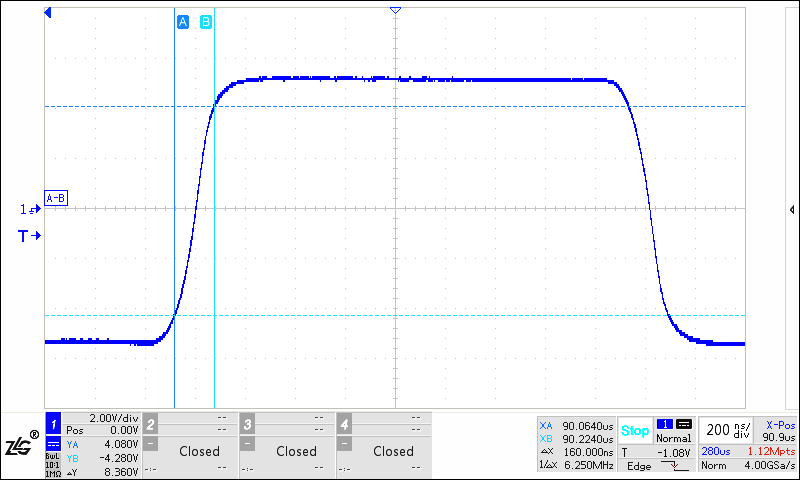
Figure 2 Differential Waveform of RSM485ECHT Single Node RS-485 Interface
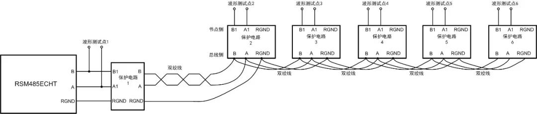
Figure3 Schematic of Bus Connected to Six Protective Circuits
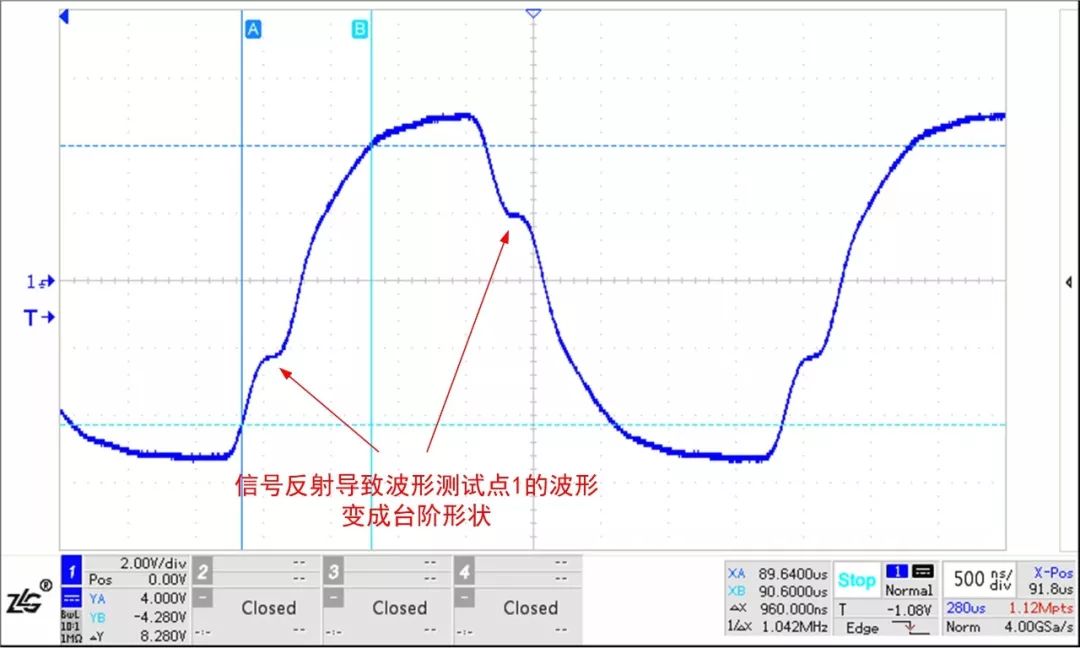
Figure 4 Waveform at Test Point 1 for RSM485ECHT Connected to Six Protective Circuits
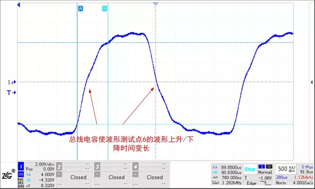
Figure 5 Waveform at Test Point 6 for RSM485ECHT Connected to Six Protective Circuits
The RS-485 interface of RSM485ECHT has strong driving capability. Below are the test waveforms of commonly used RS-485 transceiver chips in the market under the same testing conditions. It can be seen that the waveforms have been severely disturbed, and the reflected waveforms have reached close to the threshold level of the RS-485 chip, which may cause communication anomalies.Therefore, in practical applications, it is advisable to choose transceivers with strong driving capabilities.
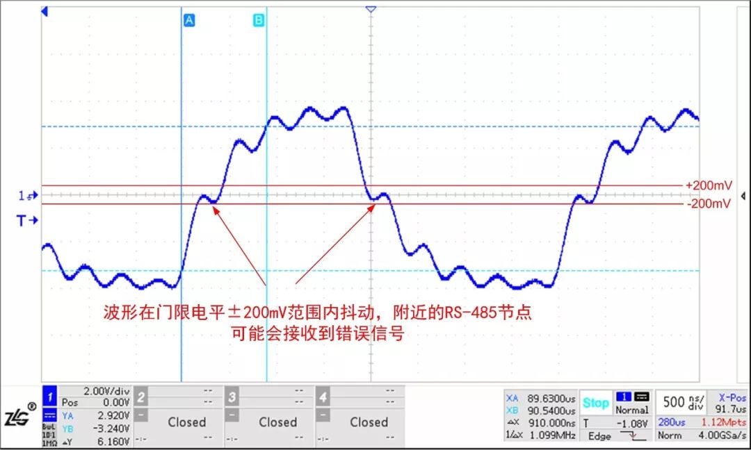
Figure 6 Waveform at Test Point 1 for an RS-485 Transceiver Connected to Six Protective Circuits

Figure 7 Waveform at Test Point 6 for an RS-485 Transceiver Connected to Six Protective Circuits
3
Low Junction Capacitance Protective Circuit
When there are many communication nodes, a protective circuit as shown in Figure 8 can be used, with the junction capacitance of A-RGND or B-RGND being only 20pF. Although the TVS junction capacitance is relatively large, the junction capacitance of ordinary diodes is very small. The junction capacitance of the TVS and ordinary diodes is in series, thus reducing the junction capacitance of the protective circuit.Using the circuit in Figure 8 for the networking shown in Figure 3, the waveform at test point 1 is shown in Figure 9, and the waveform at test point 6 is shown in Figure 10, where the waveforms have basically not changed.
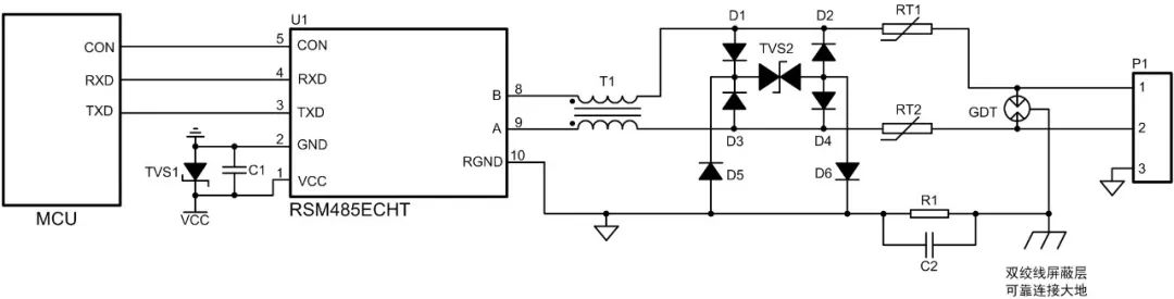
Figure 8 Protective Circuit 2 (Low Junction Capacitance)
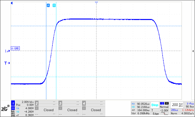
Figure 9 Waveform at Test Point 1 for RSM485ECHT Connected to Six Protective Circuit 2
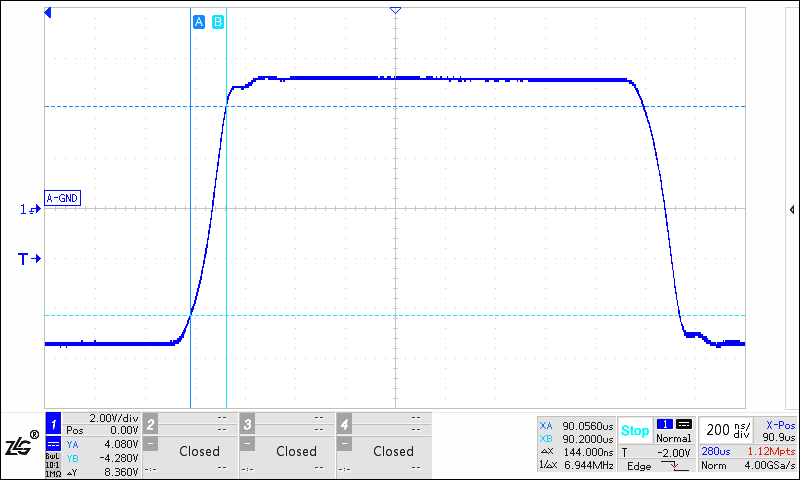
Figure 10 Waveform at Test Point 6 for RSM485ECHT Connected to Six Protective Circuit 2
4
Conclusion
The protective circuits mounted on the bus can cause changes in the instantaneous impedance experienced by the signal, leading to signal reflection. When there are many nodes on the bus, the bus capacitance becomes large, which can interfere with the bus waveform and affect communication signal quality. Therefore, to reduce the impact of protective circuits on bus communication, it is advisable to choose transceivers with strong driving capabilities in practical applications. If using the protective circuit shown in Figure 1, low junction capacitance TVS should be selected, or a low junction capacitance protective circuit as shown in Figure 8 can be used.
ZLG Zhiyuan Electronics Introduction
Guangzhou Zhiyuan Electronics Co., Ltd. is a subsidiary of Guangzhou Zhiyuan Electronics Co., Ltd., founded by renowned embedded system expert Professor Zhou Ligong in 2001. It is a nationally recognized high-tech certified enterprise and the Guangdong Provincial Engineering Technology Research and Development Center for high-end industrial control measurement instruments.
Strategy:Industrial Intelligent IoT Ecosystem
ZLG integrates “chip + AWorks software platform + artificial intelligence” from “chip” to “cloud,” designing high value-added modules, boards, and high-end measurement instruments to connect to the ZWS (ZLG Web Service) IoT cloud for big data processing, building an industrial intelligent IoT ecosystem.
Values:Professionalism and Focus Achieve Dreams
Focusing resources and concentrating on the development strategy of the industrial intelligent IoT ecosystem to achieve dreams.
Corporate Culture:Shared Struggles, Shared Benefits, Mutual Achievement
Implementing the “Climbing Plan” to build a growth mechanism for nurturing talent;
Implementing the “Partner Co-entrepreneurship and Benefit Sharing” plan to create a vibrant and positive team.