This article guide
The RS-485 bus is a half-duplex communication bus, so it usually requires an MCU to control the transmit/receive state of the RS-485 transceiver. To save MCU I/O resources, RS-485 automatic transceivers have emerged, but these types of transceivers encounter some application issues to varying degrees. How can these issues be resolved? This article will reveal the answers from the working principle.
Introduction to Automatic Transceiver Circuits and Application Analysis
Principle of Automatic Transceiver Circuits
Common RS-485 automatic transceiver circuits are shown in Figure 1, and the circuit’s logic truth table is shown in Table 1.
-
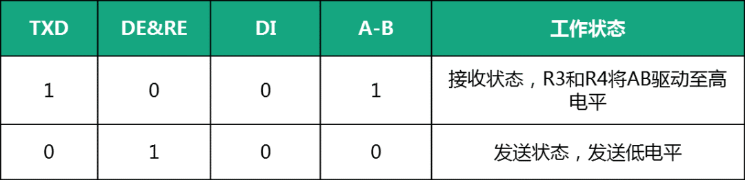
When TXD is low, DE and RE are high, and the RS-485 transceiver is in transmit mode, AB is low, which means sending a low signal to other nodes;
-
When TXD changes from low to high, DE and RE become low, and the RS-485 transceiver is in receive mode. At this time, the AB pin is in a high-impedance state, R3 pulls the B pin to GND, and R4 pulls the A pin to VCC, making AB high, which means sending a high signal to other nodes.
Since TXD is high, the RS-485 transceiver is in receive mode, so TXD only needs to be kept high to receive data, meaning that the automatic transceiver circuit is in receive mode while sending a high signal.
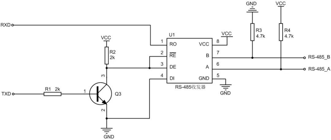
Figure 1 RS-485 Automatic Transceiver Schematic
Table 1 Automatic Transceiver Circuit Schematic
Common Application Issues and Solutions for Automatic Transceiver Circuits
01
The reasons for the slow communication speed of RS-485 automatic transceivers are mainly two:
1. If using the automatic transceiver circuit shown in Figure 1, the turn-off time of the transistor is relatively long (mainly due to the long storage time when the transistor is turned off). The turn-on delay time of the transistor in the inverting circuit shown in Figure 1 is 10.2ns, and the turn-off delay time is 1.14μs. Therefore, if TXD sends a low signal, the DE & RE pins will take a long time to rise to high, resulting in a long delay in sending the low signal, as shown in Figure 4, which takes 1.468μs.
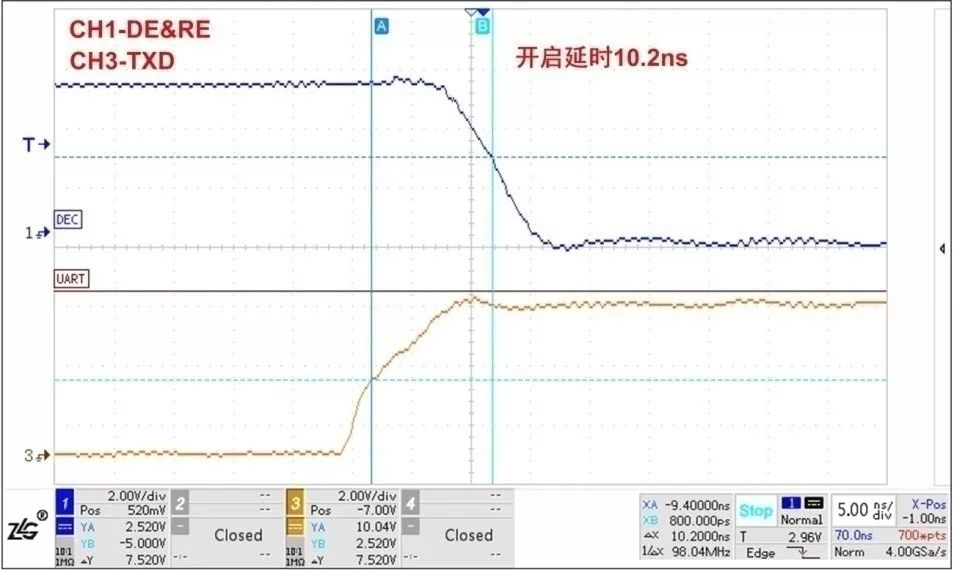
Figure 2 Turn-On Delay Time
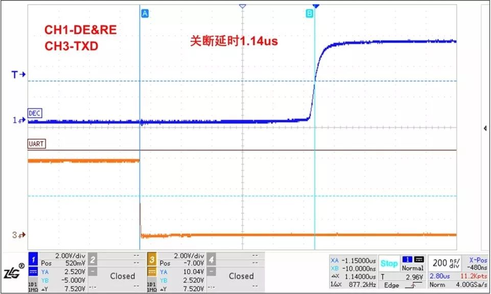
Figure 3 Turn-Off Delay Time
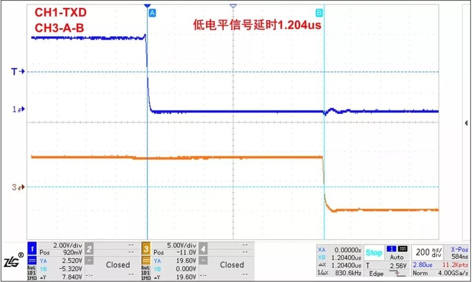
Figure 4 Low Signal Sending Delay
2. The automatic transceiver circuit sends high signals through external pull-up and pull-down resistors, resulting in slow rising edges, as shown in Figure 5. It can be seen that the rising edge of the high signal is slow, limiting high-speed communication applications.
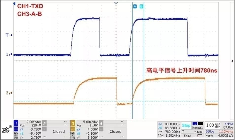
Figure 5 Rising Time of Sending High Signal
02
As shown in Figure 6, when TXD becomes high, DE & RE pins drop to low, and the AB differential voltage rises slowly. At this time, the RS-485 transceiver is already in receive mode, and before the AB differential voltage reaches the threshold level of the RS-485 transceiver, the RXD pin will output a low signal for a period. For example, for a transceiver with a threshold level of -200mV to -50mV, the RS-485 transceiver will output a low signal until the AB differential voltage rises to -50mV. This low signal duration is related to the rise time of the AB differential voltage and the receive delay of the RS-485 transceiver.
Since the serial port generally divides each bit into 16 parts and detects the level signal of the middle 3 parts to determine the high or low of this bit, if this low signal is maintained during the signal detection of each bit, it will cause the MCU to receive a start bit, thus receiving erroneous data. Therefore, this issue also limits high-speed communication applications and reduces communication reliability.
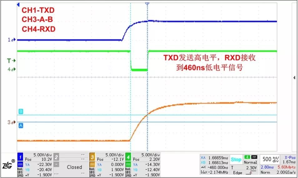
Figure 6 TXD Sends High Signal, RXD Receives Low Signal for a Period
To address these issues, you can choose the ZLG SC4450S wide-voltage input surface-mount isolated RS-485 automatic transceiver module (as shown in Figure 7). This module supports communication speeds up to 500kbps and will not output a low signal for a period when sending a high signal, as shown in Figure 8, greatly improving communication reliability.
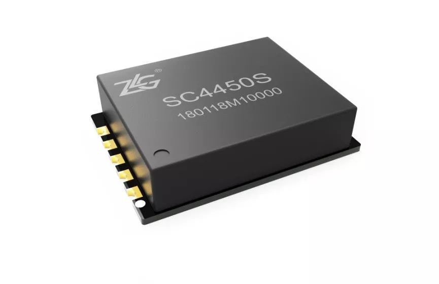
Figure 7 Surface-Mount Isolated RS-485 Transceiver SC4450S
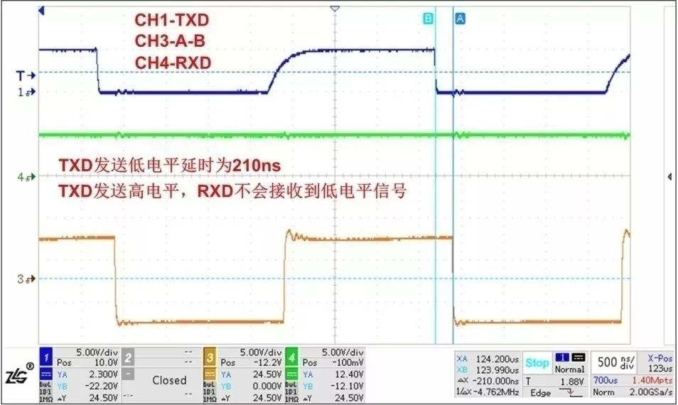
Figure 8 SC4450S Communication Waveform
03
In high electrostatic or surge environments, additional peripheral protection circuits are needed to protect the RS-485 transceiver. If the junction capacitance of the protection circuit added to the RS-485 bus is large, it will affect the quality of the communication waveform and even lead to communication anomalies. The communication waveform using high junction capacitance protection circuits is shown in Figure 9, where the waveform is severely distorted, affecting communication quality.
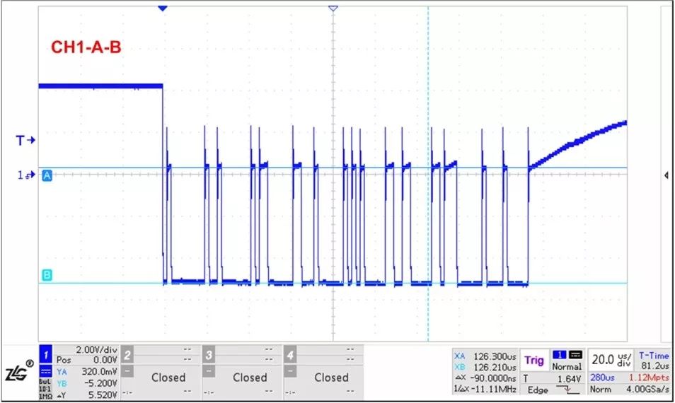
Figure 9 Waveform Affected by High Junction Capacitance
To address these issues, you can choose ZLG SC4450S, and according to the protection circuit provided in the data sheet, as shown in Figure 10, it can comprehensively enhance the protection capability of the RS-485 bus. The EMC protection capability can reach ±8kV for electrostatic contact, ±4kV for surge common mode, and ±2kV for differential mode, meeting the needs of most industrial applications.
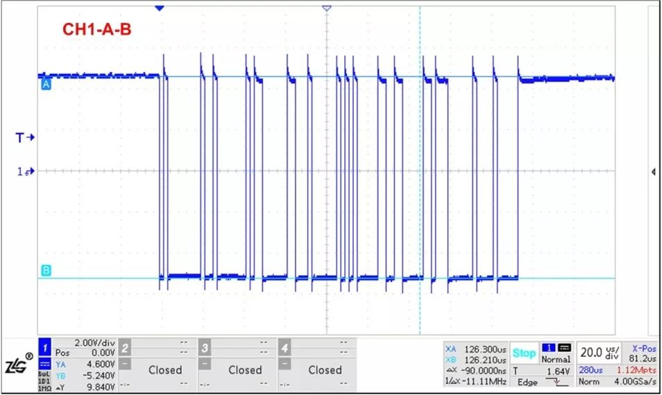
Figure 10 Low Junction Capacitance Protection Circuit

Figure 11 Communication Waveform After Adding Protection Circuit
04
When sending high signals, the automatic transceiver circuit will always have a period of time or all the time driven by pull-up and pull-down resistors. To improve the driving capability of sending high signal, smaller value pull-up and pull-down resistors should be used. However, due to the limitations of the RS-485 transceiver’s driving capability, the pull-up and pull-down resistors cannot be too small; generally, the parallel value of pull-up and pull-down resistors at all nodes on the bus should not be less than 375 ohms. Therefore, the driving capability of sending high signal in the automatic transceiver circuit is very limited. After adding terminal resistors to the RS-485 bus, the AB differential voltage of the high signal sent is obtained by the voltage divider of the terminal resistor and pull-up/pull-down resistors. Thus, the amplitude of the high signal sent is very low. Therefore, when using automatic RS-485 transceivers, it is advisable not to use terminal resistors.
Due to the limited driving capability of the automatic transceiver circuit, the communication distance it can achieve is also limited. The communication waveforms using twisted pairs of lengths 8m and 200m are shown in Figures 12 and 13. When the communication distance is 8m, the waveform is good and communication is normal; when the communication distance is 200m, it cannot communicate normally. Therefore, for longer communication distances, pull-up and pull-down resistors and terminal resistors can be added externally to improve the communication waveform. The improved communication waveform after addition is shown in Figure 14, where the waveform is greatly improved, allowing normal communication, but the amplitude of the high signal sent is still low.
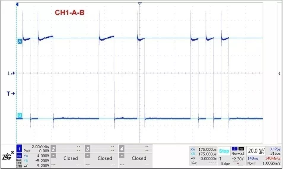
Figure 12 Communication Waveform Through 8m Twisted Pair
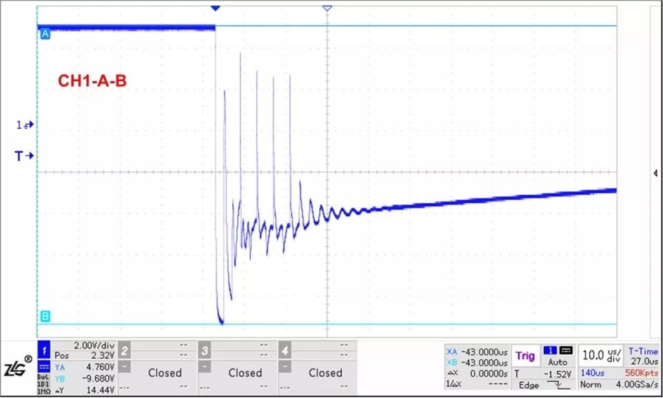
Figure 13 Communication Waveform Through 200m Twisted Pair
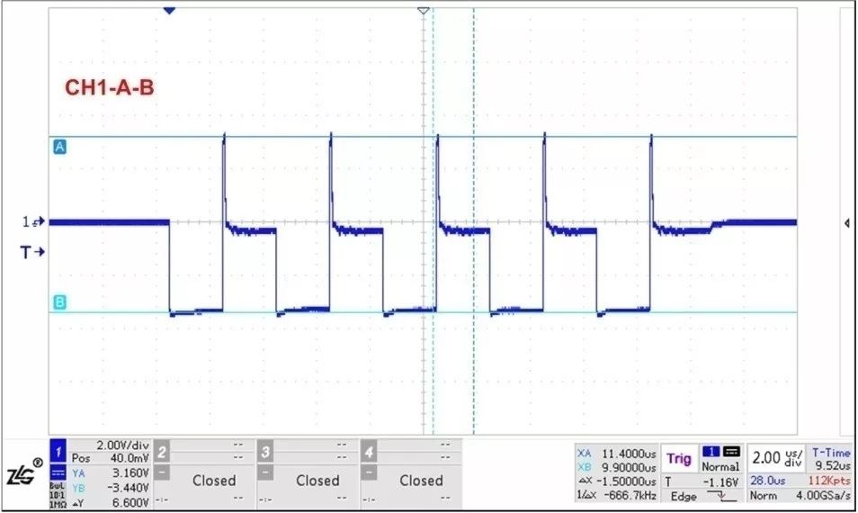
Figure 14 External Pull-Up/Down Resistors and Terminal Resistors Added to RS-485 Bus
If there are high requirements for communication distance, it is not recommended to use automatic transceiver modules. You can choose ZLG isolation RS-485 transceivers with transceiver control functions, RSM485ECHT or RSM3485ECHT, with communication distances up to 1200m. The communication speed is 500kbps, and the communication distance is 1200m. The communication waveform with 120-ohm terminal resistors at both ends of the bus is shown in Figure 15, where the amplitude of the signal sent by RSM485ECHT can reach 2.6V, greatly improving communication reliability.
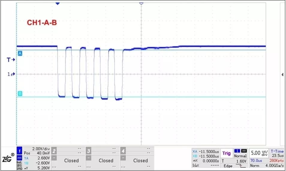
Figure 15 Communication Distance of 1200m, Terminal Resistors Added at Both Ends of the Bus, RSM485ECHT Sending Waveform
Summary
The automatic RS-485 transceiver can save MCU I/O ports and reduce the workload of programming. However, conventional automatic transceiver circuits have issues such as slow communication speed and RXD receiving a low signal for a period when sending a high signal. Therefore, if automatic transceivers are to be used, it is recommended to use the isolated RS-485 transceiver SC4450S, which greatly improves communication reliability. Coupled with the recommended low junction capacitance protection circuit of SC4450S, it can withstand higher electrostatic and surge levels, improving product reliability. For longer communication distances, it is recommended to use the enhanced isolated RS-485 transceivers RSM485ECHT/RSM3485ECHT, with communication distances up to 1200m.
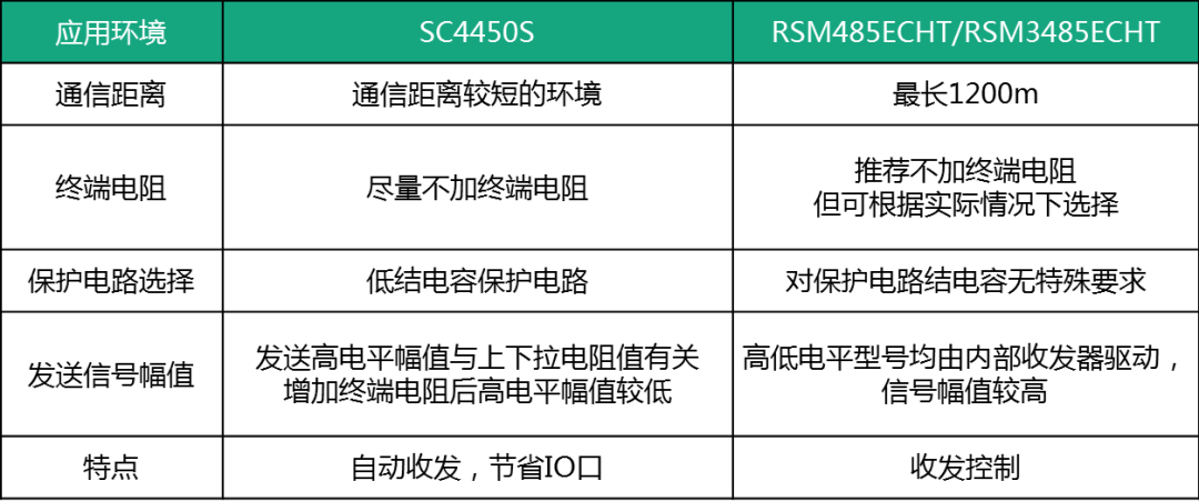
Table 2 Product Recommendation Application Situation Description
If you have any questions, please feel free to add the official ZLG customer service WeChat account for consultation: zlgmcu-888.
ZLG Electronics Introduction
Guangzhou ZLG Electronics Co., Ltd. was established in 2001 and is a national high-tech certified enterprise, as well as the Guangdong Provincial Engineering Technology Research and Development Center for high-end industrial control measurement instruments.
Vision:To become a leading enterprise in the industrial internet ecosystem
Design high value-added modules, boards, and high-end measurement instruments using the “chip + AWorks software platform” through wired and wireless interfaces to connect to the ZWS IoT cloud, achieving big data processing and forming the industrial internet ecosystem.
Mission:To promote the progress of China’s industrial internet with leading technology
Values:Professionalism and focus achieve dreams