Introduction:
The RS-485 bus is now used less frequently, but many systems still rely on it, making it necessary to learn about it.
Main Content:
1. On-site Wiring Specifications
The RS-485 bus is widely used due to its low cost and simple design, finding applications in security monitoring, intelligent transportation, smart buildings, data center monitoring, and industrial automation. Although the installation of RS-485 bus wiring is relatively straightforward, there are several important considerations to ensure reliable communication and ease of maintenance. The following are the wiring specifications compiled by Guangzhou Lian Intelligent System Development Co., Ltd. regarding RS-485 wiring:
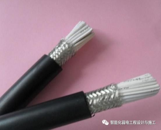
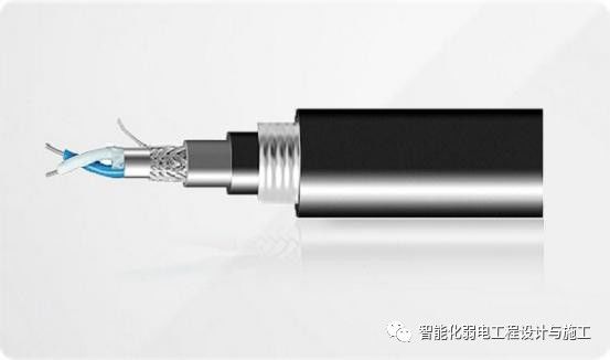
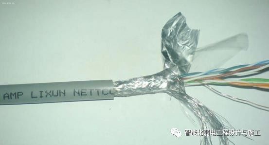
Wiring Material: The wiring for the RS-485 bus must use shielded twisted pair cables, preferably with a wire diameter of 0.75 or 1.0 mm. Many people, for convenience, directly use network cables as RS-485 wiring. Network cables have eight wires, while RS-485 only requires two or four wires, wasting the rest. Moreover, the wire diameter of current network cables is relatively thin and may not meet the communication requirements of RS-485. It is recommended not to use network cables. Parallel wires, coaxial cables, or unshielded twisted pairs should also not be used. Since RS-485 employs differential balanced transmission, using twisted pairs effectively mitigates external interference. It is crucial to avoid parallel wires for the same reason. The shielding layer helps shield against external interference, so it is best to use twisted pairs with shielding.
Wiring Issues: The RS-485 bus wiring should be kept as far away from interference sources as possible. During installation, many people, for convenience, run RS-485 lines alongside power lines, which is unreasonable. Power lines produce interference, leading to unstable RS-485 communication. Additionally, RS-485 wiring must avoid strong voltage interference sources like transformers and frequency converters.
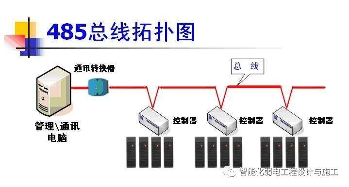
Bus Topology Issues: Due to the complexity of the on-site environment, RS-485 devices are often distributed haphazardly. For convenience, installers may not follow RS-485 specifications and instead set up the wiring in a star, tree, or mixed topology, leaving too many long branches. While pure star, tree, or mixed topologies can sometimes be used, communication is likely to be unstable. If a star or tree topology is necessary, it is advisable to use RS-485 hubs and repeaters. For related applications, refer to the RS-485 bus topology issue page.
Grounding Issues: The RS-485 bus wiring specifications emphasize the need for reliable single-point grounding. However, in practice, grounding can sometimes have adverse effects. Since RS-485 wiring requires a daisy chain connection, the shielded twisted pairs are typically connected to RS-485 devices, and the outer shielding layer is often used as a ground. If the shielding layer is not well connected, grounding may lead to unstable RS-485 signals. Therefore, RS-485 wiring must have reliable single-point grounding.
Transmission Distance Issues: The transmission distance for RS-485 is 1200 meters, subject to certain conditions: the baud rate must be below 110 Kbps, standard shielded twisted pairs must be used, wire diameter must meet specific standards, the load must consist of one RS-485 device, and there should be no strong electromagnetic interference. The transmission distance is inversely proportional to the communication baud rate and directly proportional to the wire diameter. The more loads there are, the shorter the transmission distance, and the greater the external interference, the shorter the transmission distance. It is recommended to leave redundancy in the wiring, as transmission distances may shorten due to aging, leading to unstable communication. Leaving redundancy can help mitigate this issue. When the RS-485 transmission distance exceeds 1000 meters, it is advisable to use RS-485 repeaters to extend communication distance.
Load Issues: The standard load capacity of RS-485 chips is 32 devices. However, some RS-485 chips can support up to 128 or even 400 devices, but in practice, this capacity may not be fully realized. Factors affecting the load capacity of RS-485 chips are related to the design of the RS-485 devices and the communication distance. If RS-485 devices are equipped with pull-up or pull-down resistors or surge protection devices, they can absorb voltage, significantly reducing the load capacity of that RS-485 line. Additionally, adding 120-ohm matching resistors on the RS-485 line can also affect load capacity. The longer the transmission distance, the lower the load capacity. It is also advisable to leave redundancy for load issues. When the load is insufficient, RS-485 repeaters or hubs from Shenzhen Dingxin Hongda Technology Co., Ltd. can be used to address these issues.
2. Incorrect Wiring Concepts
The RS-485 bus is widely used in video surveillance, access control intercom, building alarms, etc., due to its simple and reliable wiring. However, many incorrect concepts during the RS-485 wiring process lead to various issues. Here are some common misconceptions summarized:
1. RS-485 signal lines can run alongside high-voltage power lines. During actual installation, since wiring is often done through conduits, contractors may bind RS-485 signal lines with power lines for convenience. High-voltage lines produce strong electromagnetic signals that interfere with low-voltage signals, leading to unstable RS-485 communication.
2. RS-485 signal lines can use parallel wires or unshielded wires for wiring. RS-485 signals are transmitted using differential signaling, meaning the voltage difference between RS-485+ and RS-485- is used for signal transmission. If there is an external interference source, using twisted pairs for RS-485 signal transmission minimizes the interference effect on both RS-485+ and RS-485-, keeping the voltage difference unchanged. Similarly, shielded wires help reduce the impact of external interference.
3. Using ordinary shielded twisted pair cables (like network cables) is sufficient. Due to rising material costs, the market is flooded with inferior wires, and unscrupulous merchants may use alloys to replace copper wires, coating them with copper to deceive customers. To distinguish, check the cross-section of the cable: if it is copper-colored, it is copper wire; if it is white, it is alloy wire. Alloys are generally brittle, prone to breakage, and have much lower conductivity than copper, leading to problems during installation. It is recommended to choose standard RS-485 cables, which are shielded twisted pairs. The transmission line is not made of single-strand copper wire like network cables, but rather multiple strands twisted together, ensuring that if one strand breaks, it does not affect overall functionality.
4. RS-485 wiring can be arbitrarily configured in star or tree shapes. RS-485 wiring specifications require a daisy chain connection. If the wiring is set up in a star or tree configuration without using RS-485 hubs and repeaters, it can easily cause signal reflections and instability. Many contractors use star and tree wiring during the RS-485 installation. Sometimes the entire system is stable, but other times issues arise, often due to improper wiring. If star or tree connections are necessary due to site constraints, RS-485 hubs and repeaters from Shenzhen Fuyongtong Technology Co., Ltd. can help resolve related issues.
5. RS-485 bus must be grounded. Many technical documents mention that the RS-485 bus must be grounded, but do not specify how. Strictly speaking, the RS-485 bus must have reliable single-point grounding. Single-point means there should only be one grounding point along the entire RS-485 bus; multiple grounding points can lead to common-mode interference. Reliable grounding requires good contact of the ground wire (usually the shielding wire) to maintain consistent voltage. In practice, for convenience, wires are often cut into segments and connected, but if the shielding wire is not properly connected, the ground can become segmented, leading to inconsistent voltages and common-mode interference.
Summary by Xue Ge:
One article a day, improving a little each day, we grow and progress together!
Sharing good articles is a virtue; helping others is helping oneself.
If you encounter problems while learning about low-voltage knowledge, feel free to consult me! I am willing to provide assistance to those just entering the field.Welcome to add my WeChat: 81113907
Low-Voltage Growth Club (VIP Group) 2 is recruiting members!Low-voltage workers are welcome to join!
Our mission is to share knowledge, share resources, cooperate for mutual benefit, and grow together!
For more details, click the link below
Establishment of the Low-Voltage Growth Club (VIP) 2 Group