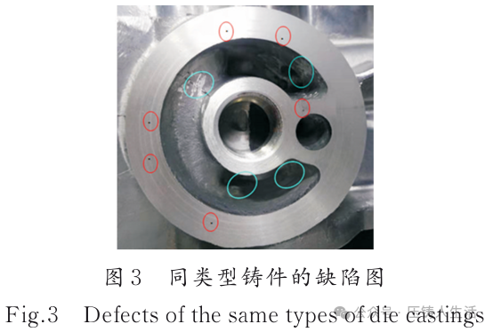
Abstract The sealing requirements at the connection between the automotive crankcase and the filter are relatively high. This area is relatively thick, large in size, and structurally complex, with uneven wall thickness, making it prone to burn and porosity defects. As a result, such parts often leak air and have relatively poor quality. Aiming to improve the quality of automotive crankcases, the use of 3D printed conformal cooling inserts for mold optimization and high vacuum die-casting processes is employed to improve the burn and porosity defect areas, thereby enhancing the quality of the castings.Keywords crankcase; sealing requirements; 3D printing; high vacuum process With the continuous increase in global energy conservation and emission reduction requirements and the rapid development of automotive technology, the demand for aluminum alloy die-castings in automobiles has shifted towards functional integration and lightweight designs, leading to increasingly complex internal component structures and higher sealing requirements for key parts. Many components exhibit significant differences in wall thickness and high sealing requirements. When casting such parts, the differences in wall thickness prevent sequential solidification, often resulting in burn and aluminum adhesion defects in thick-walled areas. Additionally, the variation in wall thickness leads to gas entrapment during the filling process, causing dense small porosity defects in the machined sealing areas. Due to the wide range of defect areas and the complexity of the part structure, localized extrusion measures cannot be used to resolve the defect issues; instead, improvements must be made to the cooling system and vacuum extraction process to address these defects. Before the advent of CAE simulation software, die-casting improvement measures and their effects lacked sufficient data support, leading technicians to rely primarily on experience to determine improvement plans, which consumed considerable time and resources.[1-3] This study takes the quality improvement of a certain automotive aluminum alloy crankcase as an example, aiming to reduce burn and porosity at the connection with the filter, and conducts virtual experiments on improvement plans. Through automatic computer calculations and result comparisons, the effects of the improvement plans on the internal quality of the parts are analyzed to determine the optimal improvement plan, shorten the development cycle of the parts, and enhance economic benefits.1. Basic Situation of the Casting Figure 1 shows a schematic diagram of the die-casting scheme for a certain automotive aluminum alloy crankcase. Based on the projected area of the casting and equipment conditions, the IDRA16 500 kN die-casting machine was selected. Preliminary calculations of the casting pouring and process parameters were made according to the characteristics of the casting: the inner gate area is 1,005 mm², the punch diameter is 120 mm, and the area ratio of the punch to the inner gate is 11.25. The aluminum liquid filling time is 0.058 s, and the total casting mass is 9.68 kg, with a mass through the inner gate of 6.6 kg. The slow punch speed is 0.2 m/s, and the fast speed is 4 m/s. The speed of the aluminum liquid at the inner gate is 45 m/s. The effective length of the pressure chamber is 700 mm, with a filling ratio of 38.3%. The theoretical high-low speed switching point is 485 mm, and the high-speed zone distance is 184 mm.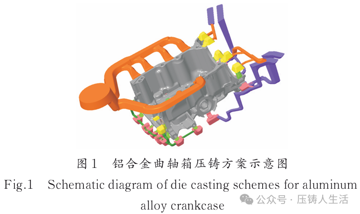 2. Description of Defects Figure 2 shows a partial view of the casting connecting to the filter. Preliminary analysis indicates that the structure of the casting at the filter connection is quite complex, with the red area (described in color based on the original image) being deep and narrow (26 mm deep, 7 mm wide). The cooling channels of the mold inserts processed using traditional techniques cannot reach the bottom and surround the area, resulting in poor cooling effects, causing severe burns and leaks in the red circle area. Similar castings not only exhibit severe burns in this location but also show exposed porosity after machining. Figure 3 illustrates the defects of similar castings, with the red circle indicating porosity defects and the blue circle indicating burn defects. Therefore, improving the cooling efficiency in this area and reducing porosity is a significant challenge in the entire die-casting process design.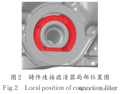
 3. Improvement of Defects The burn defects at the filter connection of similar castings are caused by excessive heat in the mold, while the porosity defects at the installation surface are caused by excessive gas content in the aluminum liquid. The factors causing these two defects are independent of each other. Therefore, the effects of metal 3D printed conformal cooling inserts and traditional cooling inserts on burn defects were first simulated using Magma software. Then, based on the insert that showed better cooling effects and could resolve the local burn defects at the filter, a simulation comparison was made with and without vacuum extraction to derive the optimal combination plan for defect resolution. It was preliminarily determined to use metal 3D printing technology to manufacture conformal cooling water channels to improve cooling efficiency and resolve burn defects. To ensure the effectiveness of the design, two sets of plans were designed using CAD. Figure 4 shows the conformal cooling insert and traditional cooling insert, with blue indicating the cooling water channels. The die-casting schemes for both inserts were imported into the Magma simulation software for simulation. By comparing the simulation results, the impact of the two plans on the risk locations was analyzed to determine whether the metal 3D printed conformal cooling insert plan is feasible for resolving the burn defects at the filter connection of the casting.
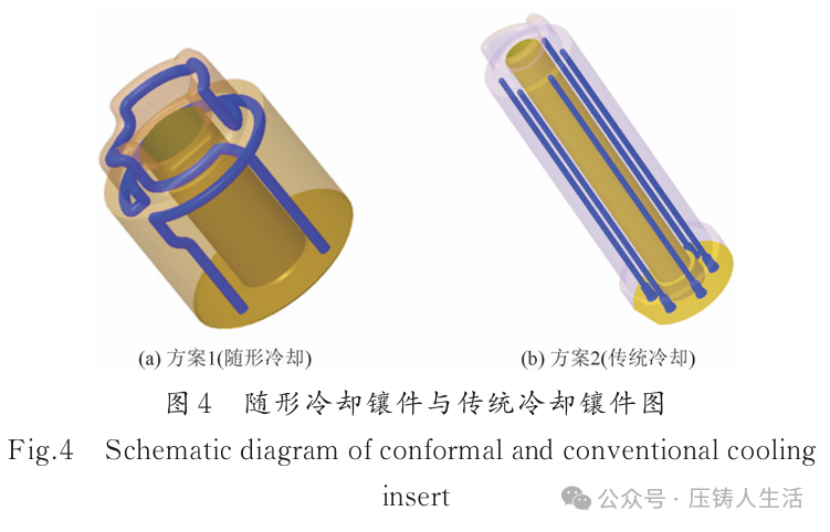 Figure 5 shows the temperature simulation comparison of the two plans, and Table 1 presents the temperature comparison data for the two plans. From the temperature analysis displayed by the simulation software, after the aluminum liquid fills the cavity 100%, it can be observed that the temperature at the forming position of Plan 1 is lower than that of Plan 2, with an average temperature difference of approximately 73.3 °C.
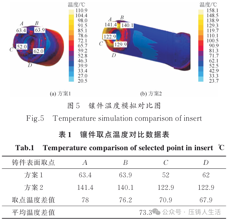 Figure 6 shows the thermal node simulation comparison of the two plans, and Table 2 presents the thermal node comparison data for the two plans. From the thermal node analysis of the solidification of the casting displayed by the simulation, it can be observed that the thermal node values of the insert in Plan 1 are lower than those in Plan 2, with an average difference of approximately 0.22 s, thus reducing the risk of shrinkage cavities caused by thermal nodes.
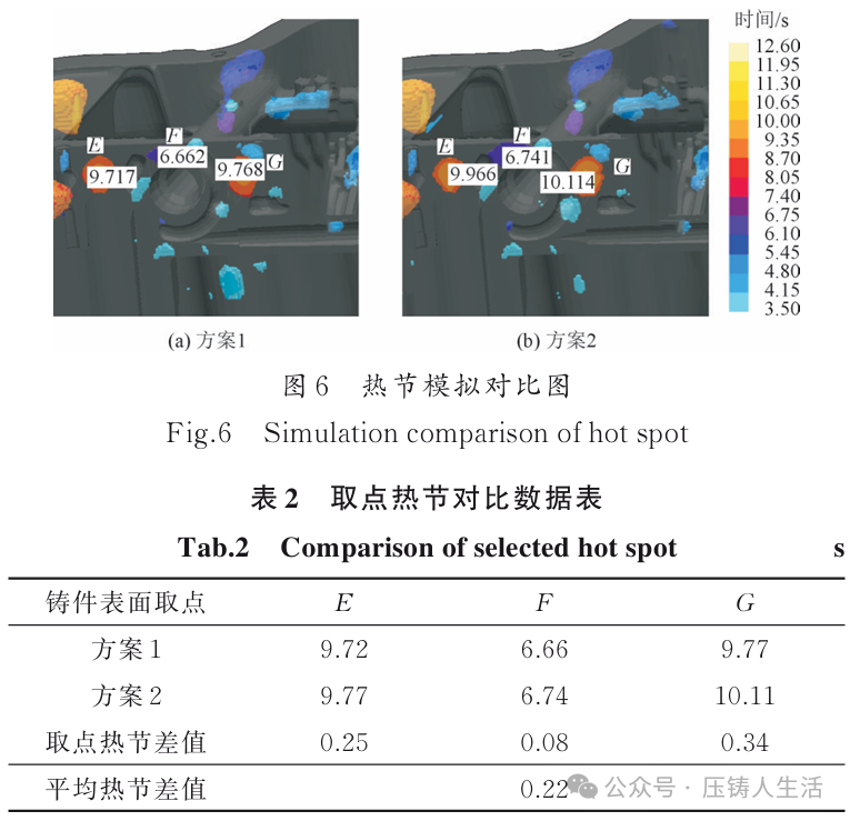 Figure 7 shows the comparison of burn adhesion between the two plans, and Table 3 presents the comparison data for burn adhesion points. From the analysis of burn adhesion during the solidification of the casting, it can be observed that the burn adhesion values of the insert in Plan 1 are lower than those in Plan 2, with an average reduction of approximately 0.62 s, thus reducing the risk caused by burn adhesion.
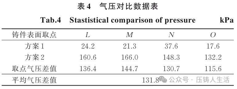
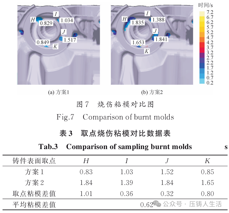 In summary, the use of metal 3D printed conformal cooling inserts results in lower temperatures, smaller thermal node values, and reduced adhesion values at the filter connection compared to traditional cooling inserts, significantly improving burn defects.4. Measures to Eliminate Porosity Defects Based on the plan using metal 3D printed conformal cooling inserts that effectively resolve local burn defects at the filter connection, two boundary conditions were added in the Magma simulation software: vacuum extraction and conventional atmospheric venting. The simulation results were then compared to verify the impact of the vacuum process versus conventional atmospheric venting on the porosity at the filter installation surface, leading to an optimized combination plan to resolve both defects. From the analysis of the simulation results, based on the comparison of the filling gas pressure of the casting, it can be observed that the vacuum extraction process in Plan 3 results in lower pressure values at the filter installation surface compared to the atmospheric venting process in Plan 4, with an average pressure reduction of approximately 131.8 kPa, thus reducing the risk of exposed porosity caused by high pressure. Figure 8 shows the pressure simulation comparison of the two plans, and Table 4 presents the pressure comparison data for the two plans. Plan 3 represents the vacuum extraction simulation, while Plan 4 represents the conventional atmospheric venting simulation.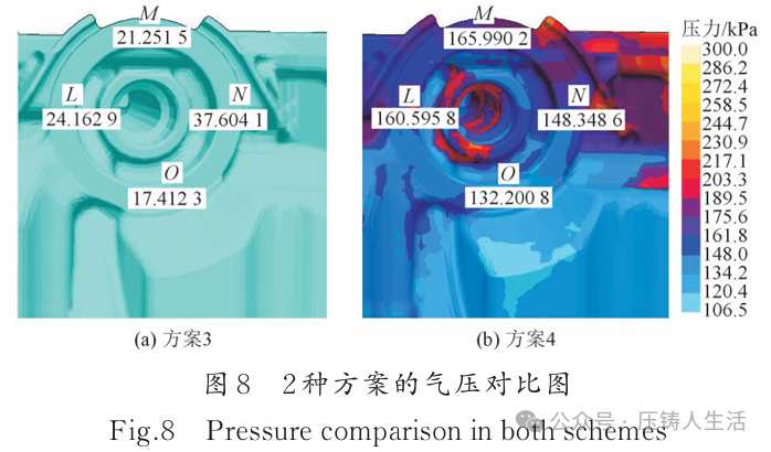
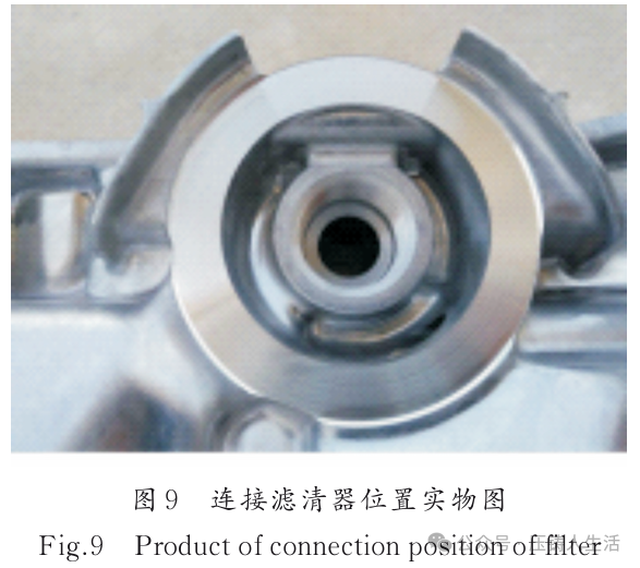
 In summary, the comparison of simulation results using Magma software indicates that the high vacuum process results in lower pressure values at the filter installation surface compared to the conventional atmospheric venting process, significantly improving porosity defects. Furthermore, the combination of metal 3D printed conformal cooling inserts and vacuum extraction processes is an ideal solution for addressing local burn defects at the casting filter connection and exposed porosity defects after machining.5. Production Verification During the die-casting production process, for the forming position of the casting connecting to the filter, it was decided to use high-carbon high-alloy steel W360 for the metal 3D printed conformal cooling inserts instead of the traditional 8418 material for direct cooling inserts, resulting in significant improvements in cooling effects and a longer service life compared to the traditional 8418 material. To enhance the vacuum extraction effect and improve the sealing performance of the mold, a sealing groove was opened at the parting line between the fixed mold core and the mold frame, and a high-temperature resistant sealing ring was installed in the sealing groove. Additionally, a sealing plate was added behind the movable mold pad, which can be fixed to the movable mold pad, and sealing grooves and buffer gas grooves were created on the sealing plate. A high-performance vacuum machine, Haivang, was used, with main dimensions of 800 mm × 1,800 mm × 1,800 mm, a system working pressure of 0~0.1 MPa, a pumping rate of 63 m³/h, and compressed air pressure of 0.55~0.6 MPa, with a compressed air volume of 300 L/min. This equipment uses a pneumatic vacuum valve, which has a large exhaust capacity during operation, is easy to install, is not easily contaminated, and has a short maintenance cycle. The die-casting trial using the combination of conformal cooling inserts manufactured by 3D metal printing technology and vacuum extraction processes resulted in a reduction in the scrap rate due to leakage caused by corner burns at the filter connection from 10% to 0% compared to similar castings. The scrap rate due to exposed porosity at the machined surface decreased from 6% to 0.5%, and the overall scrap rate dropped from 16% to 0.5%, fully meeting customer usage requirements. Table 5 presents the comparison of scrap rates, and Figure 9 shows the physical image of the filter connection position.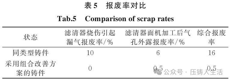
 6. Conclusion To address the issues of low local cooling efficiency and exposed porosity at the machined surface due to structural reasons in the mold, the combination of metal 3D printing technology for manufacturing conformal cooling inserts and vacuum extraction technology can significantly improve local cooling efficiency, reduce the gas content in the casting, enhance the quality of the casting, save production costs, shorten the development cycle of the casting, and improve economic benefits. The high vacuum die-casting technology is relatively mature and widely used in die-casting molds, but 3D printing technology is still in the development stage, with many issues to be resolved, such as material performance, printing accuracy, efficiency, lifespan, and cost.References:[1] Zhang Yulong, Chen Guoen, Zhu Yu, et al. Application of CAE Simulation in the Die-Casting of Automotive Engine Filters [J], Special Casting and Nonferrous Alloys, 2020, 40(12): 658-661.[2] Wu Chunmiao. Die-Casting Technology Manual [M]. Guangzhou: Guangdong Science and Technology Press, 2007.[3] Chen Guoen, Tan Xiaoming, Wang Xueyang, et al. Application of CAE Analysis in Improving the Quality of Aluminum Alloy Die-Cast Filters [J], Special Casting and Nonferrous Alloys, 2018, 38(4): 658-661.Authors:Ge Wangsheng1 An Zhaoyong2 (1. Zhaoqing Technician College, Zhaoqing 526040; 2. Guangdong Hongtu Technology Co., Ltd., Zhaoqing 526100)Source: Special Casting and Nonferrous Alloys, Issue 11, 2025