01
RFSoC Multi-Board Synchronization
Zynq™ UltraScale+ ™ RFSoC architecture combines the ZYNQ architecture with the flexibility and functionality required for direct RF sampling, providing highly reconfigurable logic and software programmability. This makes it particularly suitable for applications requiring rapid data acquisition, high-speed digital signal processing, and efficient RF communication, such as phased array radar, 5G and wireless infrastructure, radio telescopes, and test and measurement systems.
In RF applications such as phased array radar, distributed antenna systems, and MIMO networks, phase synchronization across multiple channels is crucial. These systems often employ multiple cooperating circuit boards to capture and process data from wide-area arrays or complex networks. However, this multi-board setup presents a significant challenge: synchronization. Without precise timing alignment, the system may experience data inaccuracies, signal degradation, and performance decline. Ensuring synchronization between all boards is essential for maintaining the data integrity and coherence of the entire system.
In particular, synchronization can also be achieved among different nodes located in different physical positions.
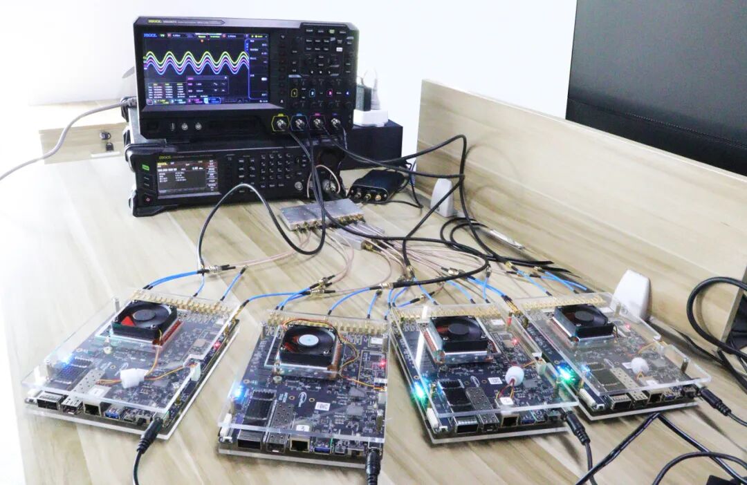
A demonstration of multi-board synchronization using T510 boards showcases the scalable, high-performance RF system of the T510 platform.
The RFSoC theoretically allows for synchronization of any number of boards; however, since the oscilloscope only has 4 channels (each RFSoC outputs one data stream), this demonstration will use four T510 boards.
Physical connection diagram of 4 T510 boards
02
03
DAC Synchronization
The 4 T510 boards’ DACs send a 100MHz signal, with the oscilloscope’s 4 channels corresponding to one DAC channel from each T510.
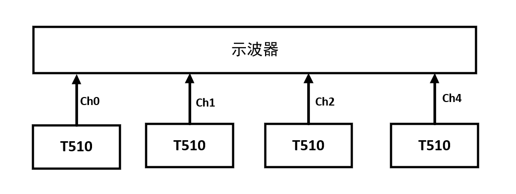
DAC connection schematic
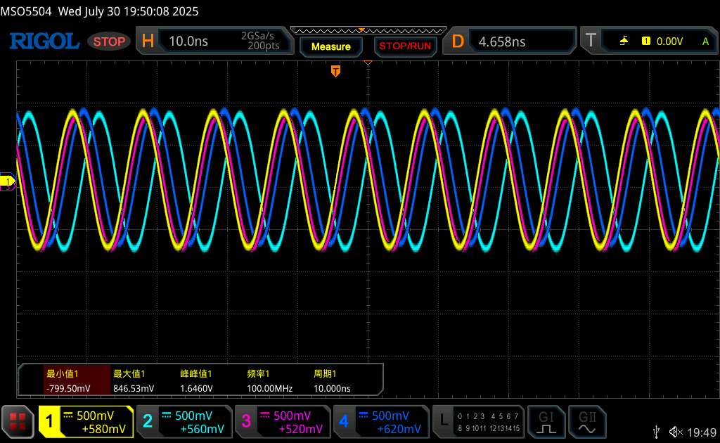
Waveforms of the 4 T510 DACs before synchronization
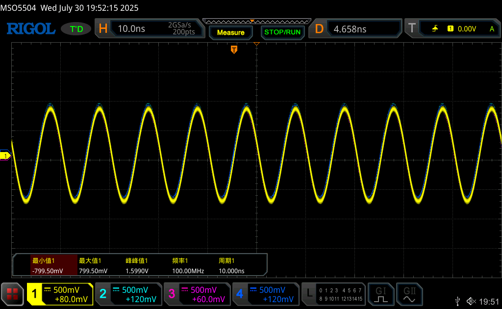
The waveforms of the 4 T510 DACs after synchronization are nearly perfectly overlapping
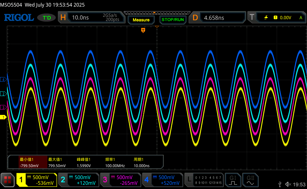
The waveforms of the 4 T510 DACs after synchronization are separated by vertical translation
ADC Synchronization
04
A 100MHz signal is generated by a signal generator, then passed through an 1-to-8 power splitter, connecting 4 T510 boards, with each T510 connected to two channels of the splitter.
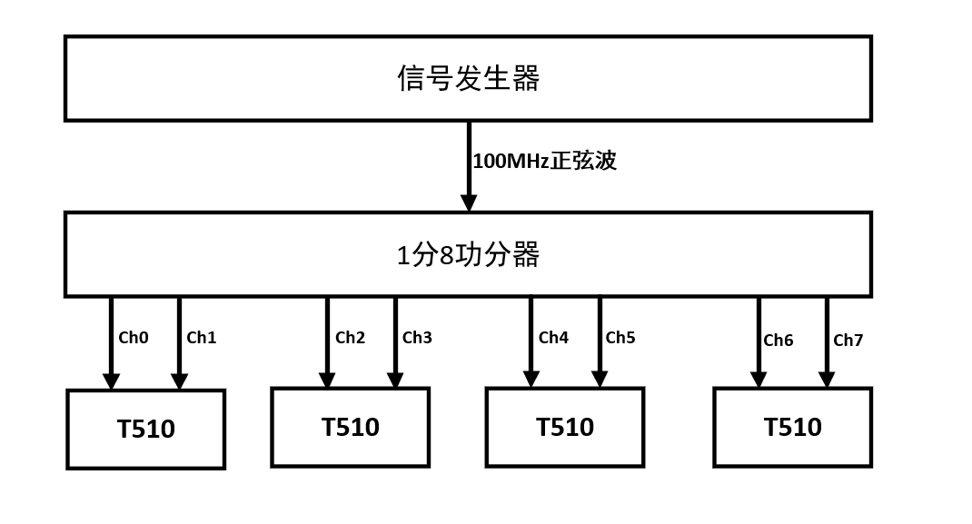
ADC channel connection schematic
Simultaneous signal acquisition yields the following results
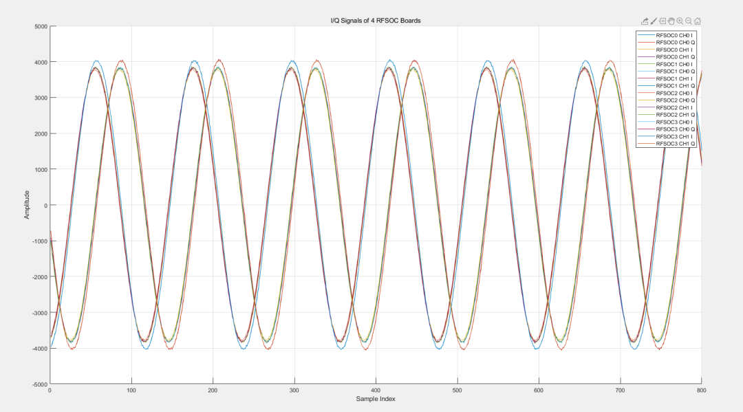
The 2 ADC channels of the 4 T510 boards acquire simultaneously
At 100MHz, without calibration, the signals are nearly perfectly overlapping; if the ADCs want better performance, calibration can be performed on each channel during post-processing, achieving a phase difference of ±3 degrees after calibration.
05
RFSoC Multi-Board Synchronization Applications

Phased Array Systems:
Achieve precise beamforming to enhance radar resolution and targeting accuracy.

5G and MIMO Networks:
Ensure coherent transmission across antenna arrays for high-throughput wireless communication.

Electronic Warfare and Signal Intelligence:
Support precise, time-aligned signal detection and analysis across multiple sensors.

Scientific Applications:
Crucial in fields such as radio astronomy and particle physics, where synchronized data acquisition ensures fidelity of distributed sensors.
 Microphase Technology
Company | Microphase Technology (Shanghai) Co., Ltd.
Address | 3rd Floor, Building 2, No. 230 Chuanhong Road, Shanghai
Website | www.microphase.cn
Phone | 021-5090-2227