RS-485 automatic transceiver circuits are favored because they use one less I/O pin compared to circuits with control pins, making them more popular in resource-constrained master control scenarios. How does the automatic transceiver achieve automatic sending and receiving, and what factors should be considered when selecting bias and termination resistors?
 RS-485 Automatic Transceiver Principle
The common RS-485 automatic transceiver circuit schematic is shown in Figure 1. The receiver enable pin RE and the transmitter enable pin DE of the transceiver are shorted to the collector of transistor Q1, the transmitter DI pin is connected to the emitter of transistor Q1 which is grounded, and the MCU’s TXD is connected to the base of transistor Q1. The following explains the working process of the automatic transceiver circuit.
When the MCU sends a 0 through TXD, transistor Q1 is off, DE is enabled, and since DI is grounded, a low level is sent at this time;
When the MCU sends a 1 through TXD, transistor Q1 is turned on, RE is enabled, and at this time the DI pin of the transceiver is in a high-impedance state relative to AB, because of the presence of pull-up and pull-down resistors on AB, the bus logic state is 1, and this node enters receive mode and sends a high level.
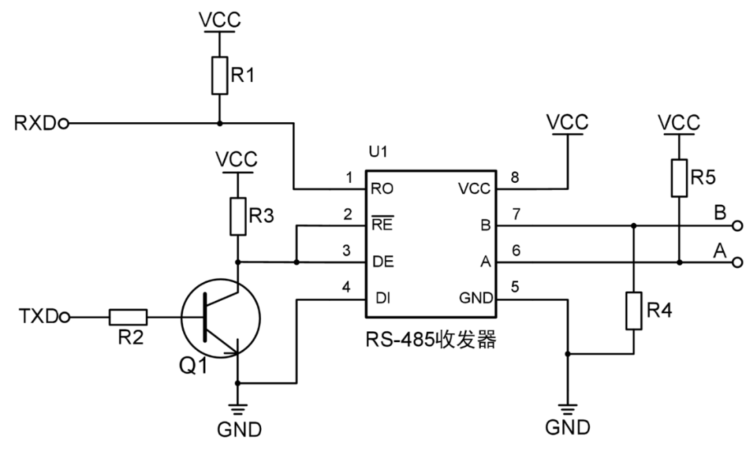
Figure 1 RS-485 Automatic Transceiver Circuit Schematic
 Role of Bias and Termination Resistors
The bias resistors of the RS-485 bus are mainly used to determine a specific logic state for A and B. Our RS-485 automatic transceiver products come with internal pull-up and pull-down resistors, and users can choose to add an external small-value pull-up or pull-down resistor to enhance driving capability based on actual application environments, such as low logic 1 voltage levels. This resistor is in parallel with the internal A/B line pull-up/pull-down resistors.
The termination resistors of the RS-485 bus are mainly used for impedance matching of the signal lines, providing a discharge path for the parasitic capacitance energy of the communication cable, and improving signal quality. The differential characteristic impedance of the commonly used RS-485 shielded twisted pair is 100Ω~150Ω. Due to the high input impedance of the RS-485 transceiver (the minimum input impedance of RSM485PHT is 1/4 unit load, i.e., 48kΩ), when the signal reaches the end of the bus, the instantaneous impedance seen by the receiver changes, causing signal reflection. Additionally, if the communication distance is long, the parasitic capacitance of the cable can be large, leading to slow energy discharge. In this case, we need to select termination resistors to eliminate or reduce the impact of this situation on the communication signal.
Since the logic 1 at the bus end of the RS-485 automatic transceiver circuit is provided by the bias resistors on AB, its driving capability is weaker than that of push-pull configurations. Therefore, the termination resistor value selected for automatic transceiver circuits is generally larger, and a small bias resistor is often added to adjust the bus voltage.
 Ideal RS-485 Bus Levels
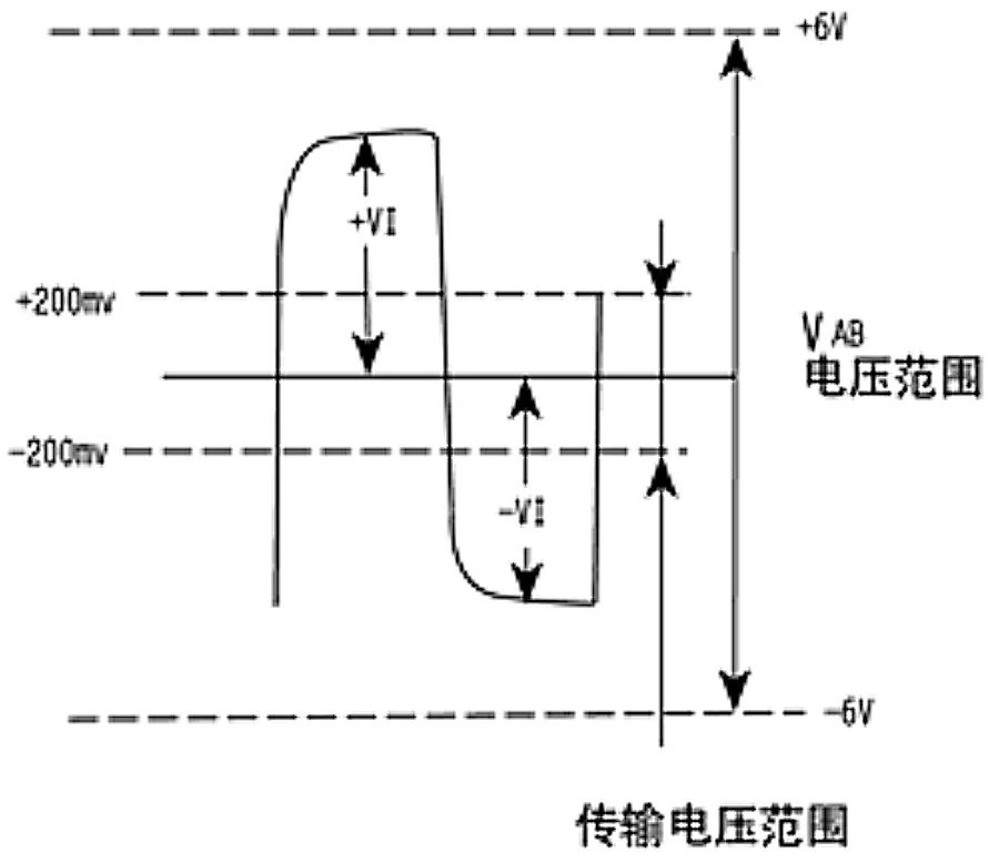
Under normal circumstances, the logic level 1 between the sending drivers A and B is between +2 to +6V, while the logic level 0 is between -2 to -6V. The receiver also has corresponding specifications relative to the sender. Generally, when the level between the receiver A and B exceeds +200mV, it outputs logic level 1, and when it is less than -200mV, it outputs logic level 0, as shown in Figure 2. During idle times, the differential level between A and B should be at logic level 1.
Figure 2 RS-485 Logic Level Diagram
Considering line resistance and signal immunity, during communication, we generally keep the logic level 1 of the bus as far away from +200mV as possible and the logic level 0 as far away from -200mV as possible. The rising and falling edges of the data waveform should be as steep as possible, and the waveform should not have overshoot or ringing. As shown in Figure 3, this is a relatively ideal RS-485 communication waveform.
Figure 3 Relatively Ideal RS-485 Communication Waveform
 Selection of Bias Resistors
This article uses our self-transmitting and receiving product RSM485PHT as an example. This product has a complete DC-DC circuit and signal isolation circuit, with strong anti-interference capability and high reliability, and features automatic sending and receiving. The A and B lines of this product have built-in 47kΩ pull-up and pull-down resistors, with a minimum input impedance of 48kΩ for the transceiver.
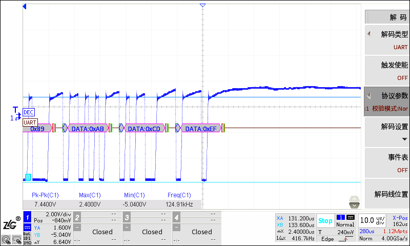
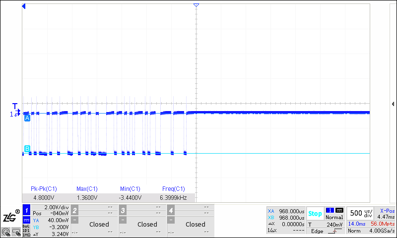
The hardware block diagram for this test is shown in Figure 4. Under a communication rate of 500kbps, with 6 communication nodes connected on the bus and a total twisted pair length of about 3m, the captured bus waveform is shown in Figure 5, where the differential voltage of logic 1 is approximately 1.60V.
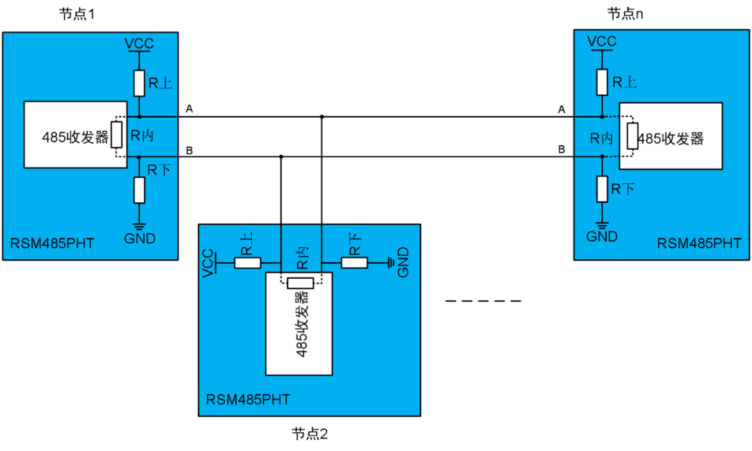
Figure 4 RSM485PHT Networking Communication Block Diagram
Figure 5 3m Twisted Pair, 500kbps VAB Waveform
The following diagram shows the equivalent circuit of the resistive voltage divider during this RSM485PHT test. When there are 6 nodes on the bus for communication, it is equivalent to having 6 Rup, 6 Rdown, and 6 Rinternal in parallel. At this time, the calculated value for the high-level voltage VAB is VAB=(Rinternal/6)/(Rup/6+Rinternal/6+Rdown/6)*VCC, taking VCC=5.1V, VAB=1.72V. Considering line resistance voltage division, this calculated value of 1.72V is consistent with the measured waveform amplitude of 1.60V.
Figure 6 RSM485PHT Resistive Voltage Divider Equivalent Diagram
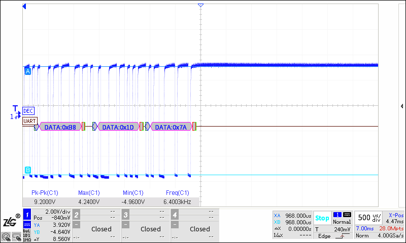
Since the logic 1 level at the bus end is only about 1.6V, this level has relatively weak immunity and affects the further extension of the communication distance. We consider adding external bias resistors to raise the bus level to around 3.5V. Using the formula VAB=(Rinternal/6)/(Rup equivalent+Rinternal/6+Rdown equivalent)*VCC, we can calculate Rup equivalent≈2.75kΩ, and the added pull-up and pull-down resistor value is approximately 4.1kΩ. Figure 7 shows the communication waveform of the bus when a 3.5kΩ pull-up and pull-down resistor is added (the added bias resistor increases power consumption by about 5.1V/3.5k≈1.4mA, which is within an acceptable range). Since the actual soldered bias resistor value of 3.5kΩ is less than 4.1kΩ, the actual bus logic 1 amplitude is 3.92V, which exceeds the preset value of 3.5V.
Figure 7 Differential Waveform when Adding 3.5kΩ Bias Resistor
 Connecting Termination Resistors of 120Ω*2
In the environment where a 3.5kΩ pull-up and pull-down resistor is connected, if we also connect 120Ω termination resistors, the equivalent resistance Rinternal equivalent≈60Ω as shown in the previous equivalent diagram 6. Substituting these values into VAB=(Rinternal equivalent)/(Rup equivalent+Rinternal equivalent+Rdown equivalent)*VCC, we calculate the voltage to be about 60mV. The test waveform is shown in Figure 8. At this time, the high level is within the threshold of -200mV~+200mV, and the transceiver cannot recognize logic 1, causing communication errors.
Figure 8 Differential Waveform when Connecting 120Ω Termination Resistors
 Conclusion
When using our automatic transceiver modules RSM485PHT or RSM485M, if the bus logic 1 level is low, you can adjust the bus level by adding external bias resistors. If the bias resistor value is too small, it will increase additional power consumption, while if the resistor value is too large, the adjustment effect will not be significant. The bias resistor value can be calculated based on the actual number of nodes to determine the equivalent resistance, and then substituted into the impedance voltage division formula (VCC*Rinternal equivalent)/(Rup equivalent+Rinternal equivalent+Rdown equivalent)=VAB, where VCC can be taken as 5.1V, and VAB is generally taken as 2.5V~4.0V.
Modules with automatic sending and receiving functions, such as RSM485PHT or RSM485M, have their bus logic 1 level driven by the bias resistors on the AB lines, which is weaker than push-pull driving. Therefore, in general, we do not recommend users to add termination resistors. If the communication rate is high, the communication distance is long, and the bus signal quality is poor, termination resistors can be added to weaken reflected signals or provide a discharge path for parasitic capacitance energy. In such cases, slightly larger resistor values can be chosen, and it can also be considered to add small-value bias resistors on the AB lines to jointly adjust the bus levels.
In summary, when using automatic RS-485 communication, it is essential to ensure that the differential voltage between A/B lines does not fall within the range of -200mV to +200mV; if the differential level amplitude of logic 1 or logic 0 is low, it can be adjusted by adding small bias resistors; generally, users are not recommended to add termination resistors, but if they do, it is advisable to choose a larger resistance value and use it in conjunction with external bias resistors.
 Related Products