1. The wiring between RS-232 and TTL mainly involves voltage conversion, as RS-232 uses negative logic levels (+3V to +15V represents logic low, -3V to -15V represents logic high), while TTL uses positive logic levels (0V represents logic low, 3.3V or5V represents logic high).When no data is transmitted on the serial data line, it is in an idle state: both TX and RX are at high level.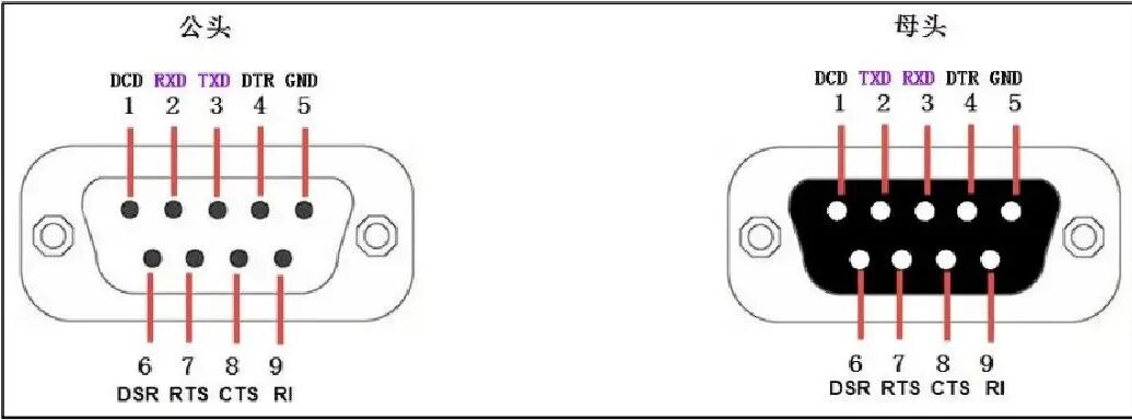
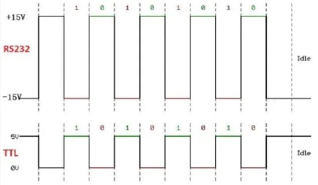 2. The voltage standards of RS-232 and TTL interfaces are different and cannot be directly connected; a conversion chip is required for level conversion. Some may ask:What happens if TTL is directly connected to RS-232? The answer:TTL and RS-232 are incompatible,Connecting TTL to RS-232 will cause system failure.
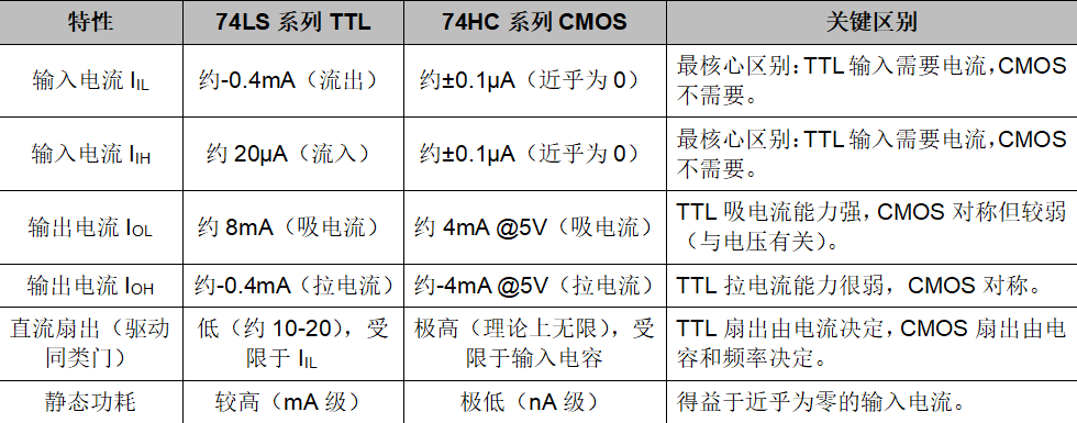
1.The input stage of a TTL circuit is a multi-emitter transistor, so there is always current flowing in the input circuit;The output stage is a “totem pole” structure, which can provide (Source) and absorb (Sink) current, but the ability to absorb current is usually stronger.2.The input stage of a CMOS circuit is an insulated gate field-effect transistor (MOSFET) gate, which is insulated, so the DC impedance is extremely high under static conditions;The output stage is a complementary series structure of P-channel and N-channel MOSFETs. Its output current capability is closely related to the power supply voltageVCC .3. The TTL andRS-232 level switching circuit
In practice, you will encounter communication states between TTL andRS-232 levels. To achieve a convenient switching method, a circuit is provided for everyone to use:
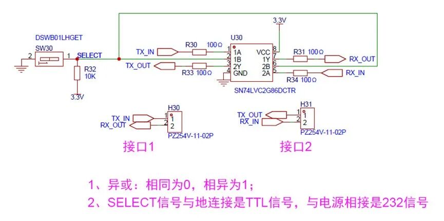 1.Connecting SELECT to ground selects the TTL interface, while connecting to power selects the RS-232 interface.
When SELECT is connected to 3.3V: TX_IN inputs high level, RX_OUT outputs low level ; TX_IN inputs low level, RX_OUT outputs high level; The signal of RX_IN follows the same principle, belonging to the 232 communication logic;
When SELECT is connected to GND: TX_IN inputs high level, RX_OUT outputs high level; TX_IN inputs low level, RX_OUT outputs low level; The signal of RX_IN follows the same principle, belonging to the TTL communication logic.
3. A 100R or 1K resistor should be placed in series on the signal line for current limiting, as the external high level range is +3 to +15V.
The advantage of the above level switching circuit is that it allows for logical level selection, while the disadvantage is that the levels are not standard, and there may be compatibility issues; long-distance transmission (over 1 meter) is not very reliable.
4. People often ask: How to control the serial port to transmit hexadecimal when needed? How to control the serial port to transmit decimal when needed? The display on the debugging assistant showshexadecimal orASCII characters. What base are these data in during transmission?
1. The “native language of the computer world is binary, and hexadecimal is just a shorthand for convenience.
Whether it is a computer or a microcontroller, their native language is binary. All data will ultimately be converted into0 and1 level signals at the hardware level. When you send data via the serial port, regardless of whether you are sending numbers, letters, or special symbols, it will ultimately become a series of0 and1.
2. When we use the serial port debugging assistant, what we see is hexadecimal orASCII code display, which is just a “real-time translation” done by the software: selectingHEX mode: displays in hexadecimal form; selecting text mode: displaysASCII characters.Regardless of what data is transmitted, it is ultimately binary transmission. As for what is displayed on the screen as letters, symbols, decimal, or hexadecimal, that is processed by the display after the serial port receives the data, not the data directly sent from the serial port.
The essence of hardware transmission: it is always a binary bit stream, that is, 0 and1 combinations. The display method can be selected: debugging tools can display in hexadecimal, decimal, orASCII code. When programming, it is important to note: sending0x41 and sending65 (decimal) are actually the same binary data.
3.It is recommended to use hexadecimal mode during debugging, which can avoid the following issues: ASCII mode will display0x00 as blank; it allows you to visually see the true value of each byte; it is convenient for checking key information such as packet headers and checksums.
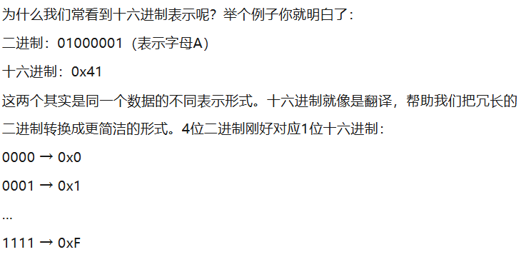
The serial port debugging assistantHEX display, remember these three points: each hexadecimal number represents4 bits of binary; the data transmission rate (baud rate) determines how many binary bits are sent per second; the data bit length (such as8 bits) determines how many binary bits are included in each data packet.