IntroductionSerial port is short for serial port (serial port), also known as serial communication interface or COM interface. Serial communication refers to a communication mode that uses serial communication protocol to transmit data bit by bit over a single signal line. Serial ports are classified according to electrical standards and protocols, including RS-232-C, RS-422, RS485, etc.
|
(1) Serial Communication |
In serial communication, data is transmitted on a single line that is 1 bit wide, and a byte of data is divided into 8 parts, transmitted in order from low to high bit.The data in serial communication is transmitted bit by bit, and each bit sent by the sender has a fixed time interval, which requires the receiver to receive each bit at the same time interval as the sender. Moreover, the receiver must also be able to determine the start and end of a group of information.The two commonly used basic serial communication methods include synchronous communication and asynchronous communication.
1.1 Synchronous Serial Communication
Synchronous communication (SYNC: synchronous data communication) means that at the agreed communication rate, the clock signal frequency and phase of the sender and receiver remain consistent (synchronous), ensuring that both parties have a completely consistent timing relationship when sending and receiving data.Synchronous communication groups many characters into an information group (information frame), with the start of each frame indicated by a synchronization character, and only one frame of information is transmitted at a time. Additionally, a clock signal must be transmitted along with the data so that the receiver can determine each information bit using the clock signal.The advantage of synchronous communication is that the number of bits transmitted is almost unlimited, with data transmission ranging from dozens to thousands of bytes, resulting in high communication efficiency. The disadvantage is that it requires precise synchronization of the clock throughout the communication, meaning the sending clock and receiving clock must be strictly synchronized (commonly, both devices use the same clock source).In the subsequent discussions of serial communication and programming, only asynchronous communication will be discussed, so we will not elaborate on synchronous communication here.1.2 Asynchronous Serial Communication
Asynchronous communication (ASYNC: asynchronous data communication), also known as start-stop asynchronous communication, transmits data on a character basis, with no fixed time interval requirements between characters, while each bit within a character is transmitted at a fixed time.
In asynchronous communication, synchronization between the sender and receiver is achieved by setting start and stop bits in the character format. Specifically, before an effective character is formally sent, the sender first sends a start bit, followed by the effective character bits, and finally sends a stop bit at the end of the character. The start bit to the stop bit constitutes a frame. The idle bits between the stop bit and the next start bit can be of variable length, and the start bit is defined as low level (logical value 0), while the stop bit and idle bits are high level (logical value 1), ensuring that there is a falling edge at the start of the start bit to mark the beginning of a character transmission. Thus, the start and stop bits easily facilitate character definition and synchronization.
Clearly, in asynchronous communication, the sender and receiver can control data transmission and reception with their respective clocks, and these two clock sources can operate independently without synchronization. Below is a brief description of the data sending and receiving process in asynchronous communication.
1.2.1 Data Format of Asynchronous Communication
Before introducing the data sending and receiving process of asynchronous communication, it is necessary to clarify the data format of asynchronous communication.
Asynchronous communication specifies that the data format for transmission consists of a start bit, data bits, parity bit, and stop bit, as shown in Figure 1 (the parity bit is not shown in the figure because it is optional; if present, it should be placed after the data bits and before the stop bit).
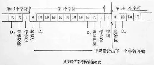
(1) Start Bit: The start bit must be a logic 0 level lasting one bit time, marking the beginning of a character transmission. The receiver can use the start bit to synchronize its receiving clock with the sender’s data.
(2) Data Bits: Data bits follow the start bit and contain the actual useful information in communication. The number of data bits can be agreed upon by both parties, generally being 5, 7, or 8 bits; the standard ASCII code is 0~127 (7 bits), and the extended ASCII code is 0~255 (8 bits). When transmitting data, the low bit of the character is sent first, followed by the high bit.
(3) Parity Bit: The parity bit occupies only one bit and is used for odd or even parity checking; it is optional. If odd parity is used, the total number of logical high bits transmitted must be odd; if even parity is used, the total must be even.
For example, if the transmitted data bits are 01001100, the parity bit for odd parity would be 0 (to ensure an odd number of 1s), while for even parity it would be 1 (to ensure an even number of 1s).
Thus, the parity bit serves only to set a logic high or low state for the data, without making substantial judgments on the data. The benefit of this is that the receiving device can know the state of a bit, potentially determining whether noise has interfered with the communication and whether the transmitted data is synchronized.
(4) Stop Bit: The stop bit can be 1 bit, 1.5 bits, or 2 bits, and can be set by software. It must be a logic 1 level, marking the end of a character transmission.
(5) Idle Bit: The idle bit refers to the state from the end of one character’s stop bit to the start of the next character’s start bit, indicating that the line is in an idle state and must be filled with a high level.
1.2.2 Data Sending Process of Asynchronous Communication
After clarifying the data format of asynchronous communication, data can be sent according to the specified data format. The specific steps for sending data are as follows:
(1) After initialization or when there is no data to send, the sender outputs logic 1, allowing for any number of idle bits.
(2) When data needs to be sent, the sender first outputs logic 0 as the start bit.
(3) The sender then begins to output the data bits, starting with the lowest bit D0, followed by D1, and finally the highest bit of the data.
(4) If a parity bit is set, the sender outputs the parity bit.
(5) Finally, the sender outputs the stop bit (logic 1).
(6) If there is no information to send, the sender outputs logic 1 (idle bit). If there is information to send, it returns to step (2).
1.2.3 Data Receiving Process of Asynchronous Communication
In asynchronous communication, the receiver determines the time length of each bit based on the receiving clock and baud rate factor. Below is an example with a baud rate factor of 16 (the receiving clock shifts the receiving shift register once every 16 clock cycles).
(1) Communication begins with the signal line idle (logic 1). When a transition from 1 to 0 is detected, the receiver starts counting the receiving clock.
(2) When 8 clock counts are reached, the input signal is checked. If it remains low, it confirms this is the start bit, not interference.
(3) After detecting the start bit, the receiver samples the input signal every 16 receiving clocks, taking the corresponding value as the D0 bit data.
(4) The receiver continues sampling the input signal every 16 receiving clocks, taking the corresponding values as D1 bit data, until all data bits are input.
(5) The parity bit is checked.
(6) After receiving the specified number of data bits and the parity bit, the communication interface circuit expects to receive the stop bit (logic 1). If logic 1 is not received, it indicates an error, and the “frame error” flag is set in the status register; if there are no errors, all data bits are checked for parity. If there is no parity error, the data bits are retrieved from the shift register and sent to the data input register. If there is a parity error, the “parity error” flag is set in the status register.
(7) Once the entire frame of information is received, the high level on the line is treated as an idle state.
(8) When the signal changes to low again, the detection for the next frame begins.
The above outlines the entire process of data sending and receiving in asynchronous communication.
1.3 Basic Concepts of Serial Communication
To better understand serial communication, we need to grasp several basic concepts within it.
(1) Sending Clock: When sending data, the data to be sent is first placed into the shift register, and then, under the control of the sending clock, the parallel data is shifted out bit by bit.
(2) Receiving Clock: When receiving serial data, the rising edge of the receiving clock samples the received data, performing data bit detection, and shifting it into the receiver’s shift register, ultimately forming parallel data output.
(3) Baud Rate Factor: The baud rate factor refers to the number of clock pulses required to send or receive one data bit.
|
(2) Serial Connectors |
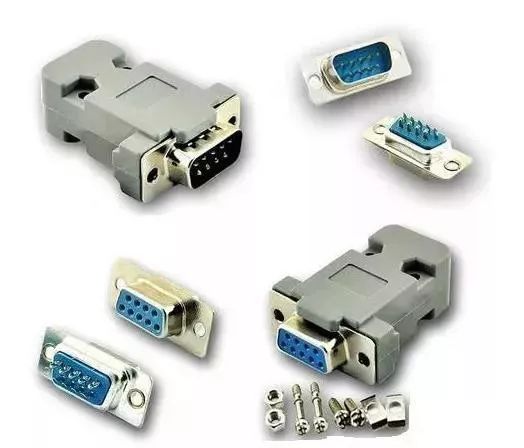
Common serial connectors come in two types: a 9-pin serial port (DB-9) and a 25-pin serial port (DB-25). Each connector has male and female variants, with the pin-type connector being male and the hole-type connector being female.
| (3) RS-232C Standard |
Common serial communication interface standards include RS-232C, RS-422, RS-423, and RS-485. Among these, RS-232C defines the electrical standard for serial communication interfaces, specifying the interface information for bit-wise serial transmission between data terminal equipment (DTE: data terminal equipment) and data communication equipment (DCE: data communication equipment), reasonably arranging the electrical signal and mechanical requirements of the interface, and has been widely used worldwide.3.1 Electrical CharacteristicsRS-232C specifies electrical characteristics, logical levels, and various signal functions as follows:On the TXD and RXD data lines:(1) Logic 1 is -3 to -15V.(2) Logic 0 is 3 to 15V.On control lines such as RTS, CTS, DSR, DTR, and DCD:(1) Active signal (ON state) is 3 to 15V.(2) Inactive signal (OFF state) is -3 to -15V.Thus, RS-232C uses positive and negative voltages to represent logical states, which is the opposite of the transistor-transistor logic (TTL) that represents logical states with high and low levels.3.2 Signal Line DistributionThe RS-232C standard interface has 25 lines, including 4 data lines, 11 control lines, 3 timing lines, and 7 spare and undefined lines. So how are these signal lines distributed among the pins of the 9-pin and 25-pin serial ports?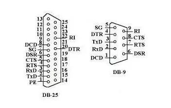 Below is a brief introduction to these signal lines:(1) Data Set Ready (DSR), active state (ON) indicates that the data communication equipment is ready to use.(2) Data Terminal Ready (DTR), active state (ON) indicates that the data terminal equipment is ready to use.These two device status signals indicate that the devices themselves are available but do not indicate whether the communication link can begin communication; whether communication can start depends on the following control signals.(3) Request to Send (RTS), indicates that the data terminal equipment (DTE) is requesting the data communication equipment (DCE) to send data.(4) Clear to Send (CTS), indicates that the data communication equipment (DCE) is ready to send data to the data terminal equipment (DTE) in response to the RTS signal. RTS and CTS are used in half-duplex communication systems; in full-duplex systems, RTS and CTS signals are not needed and can be set to ON directly.(5) Data Carrier Detect (DCD), indicates that the data communication equipment (DCE) has established a communication link, notifying the data terminal equipment (DTE) to prepare to receive data.(6) Ring Indicator (RI), becomes active (ON) when the data communication equipment receives a ringing call signal from the exchange, notifying the terminal that it has been called.(7) Transmit Data (TXD), the data terminal equipment (DTE) sends serial data to the data communication equipment (DCE) through this signal line.(8) Receive Data (RXD), the data terminal equipment (DTE) receives serial data sent from the data communication equipment (DCE) through this signal line.(9) Ground (SG, PG), representing signal ground and protective ground signal lines.
What Everyone is Watching
 [Video] How German Engineers Make PLC Cabinets?
[Video] How Are German Witte Electrical Cabinets Produced?
[Video] What Is the Work Environment Like for German Engineers?
[Video] Why Is PROFINET Better Than PROFIBUS?