 In the previous article, we briefly introduced some content about the I²C Standard-mode, Fast-mode, and Fast-mode Plus rate modes and arbitration. This article will discuss clock synchronization (Clock synchronization) and clock stretching (Clock stretching). In the previous article, we learned that arbitration is related to the SDA data line, and a similar mechanism exists on the clock line SCL, which is clock synchronization. Since the author did not introduce the concept of wired-AND in the previous articles, to facilitate understanding, the author will introduce it along with the open-drain connection structure of I²C. As shown in the figure, when two controllers attempt to control the bus simultaneously, the internal situation is as shown below.
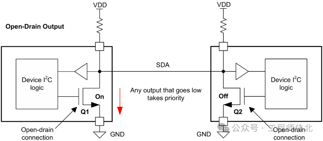 Regardless of how many I²C controllers are trying to seize control, as long as one controller’s NMOS is conducting, the bus will be pulled low.
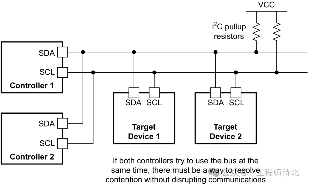 This is the characteristic of the open-drain connection, where the digital logic is a logical AND circuit, and the truth table for the above figure is as follows.
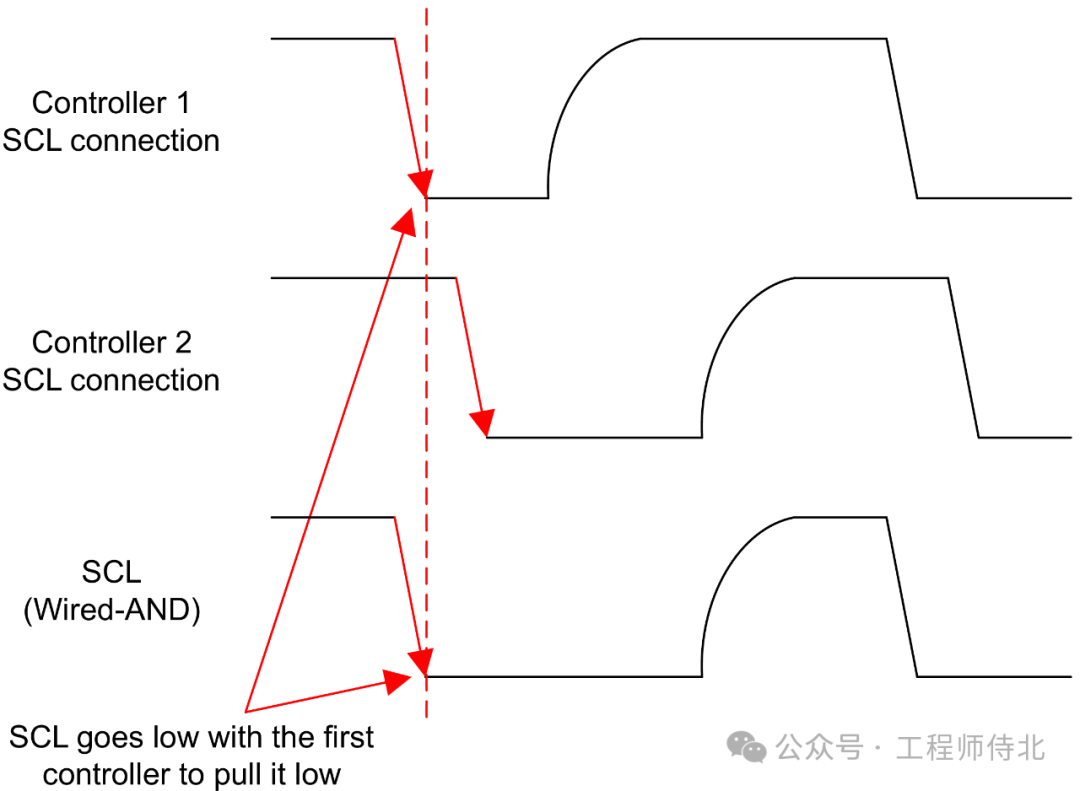
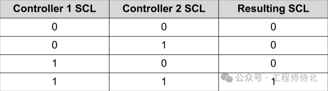 Understanding that the I²C line logic is an AND operation makes it easier to understand clock synchronization. As shown in the figure, when two controllers pull the clock line low simultaneously, since controller 1 pulls the clock line low first, SCL will immediately become low when controller 1 pulls it down.
 After controller 1 stops pulling low, since controller 2 has not released the bus, SCL remains low, as shown in the figure.
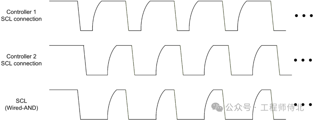
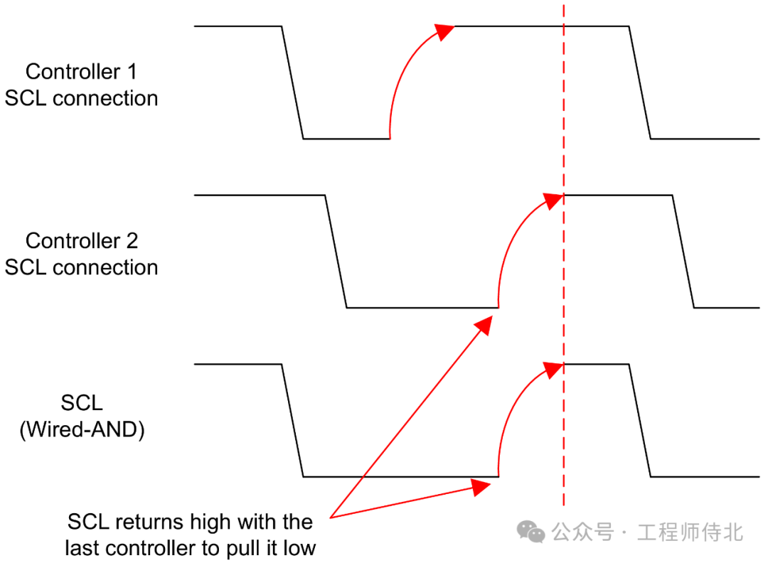 Only when all controllers on the bus release the bus will SCL return to a high state. The resulting synchronized clock signal is shown in the figure, where the low period of the clock is determined by the controller with the longest low period on the bus, while the high period of the clock is determined by the controller with the shortest high period on the bus.
 A few points to understand are: First, clock synchronization and arbitration occur under the Standard-mode, Fast-mode, and Fast-mode Plus rates. Second, these two mechanisms occur simultaneously, meaning they only happen when multiple controllers exist on the bus, and once they occur, they often happen at the same time. Third, these two mechanisms are based on the I²C’s own AND logic, and the controllers must have the ability to monitor the bus and respond when the bus level does not match their expected state. Based on the third point, we will continue to introduce clock stretching. At times, if the target device needs more time to process commands and send data from the controller, the target device will slow down the communication speed through clock stretching. As shown in the figure.
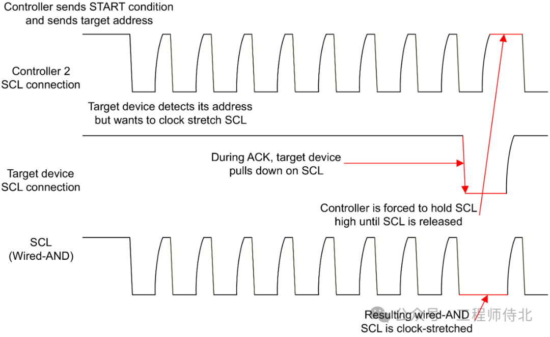 When the controller sends a byte (1 byte = 8 bits) of data, during the acknowledgment bit (ACK, Acknowledge), the target device can pull SCL low, and when the controller detects this situation on SCL, it will pause sending the next byte of data. After the target device releases SCL, the controller will continue to send data. Throughout this process, data transmission will be delayed due to clock stretching, but it will not be interrupted. The content of this article is partially sourced from NXP and the internet. If there is any infringement, please contact the author for deletion. This is for technical exchange only, and the author does not bear any responsibility for any errors.