Click the blue text above to follow us Receive 20 automation benefits, limited to 200 people, valid for 2 weeks. Claim now
Claim | Zhejiang University DCS Configuration Tutorial Video
Claim | Holley DCS Configuration Tutorial Video
Claim | Siemens PLC Configuration Tutorial Video
Claim | 10 DCS Books + 10 Instrument Maintenance Books
Claim | 132 Instrument Manuals
▲
 Click the blue text above to claim benefits
Serial communication is the most basic communication method faced by electrical engineers, and RS-232 is the simplest among them. Many beginners often struggle to understand the relationship and differences between UART and RS-232, RS-422, RS-485. This article will discuss the understanding of these concepts to help clarify their relationships.
If we compare serial communication to traffic, UART is like a station, and a frame of data is like a car. Cars on the road must obey traffic rules. If in the city, the speed limit is generally 30 or 40, while on the highway it can reach 120. The road cars take and the speed limits depend on the protocol’s specifications. Common serial protocols include RS-232, RS-422, RS-485; what are the subtle differences between them? Let’s explore together.
1. What is UART
UART stands for Universal Asynchronous Receiver/Transmitter, commonly referred to as UART, is a key module for asynchronous communication between devices. UART is responsible for handling the serial/parallel and parallel/serial conversion between the data bus and the serial port, and it specifies the frame format; as long as both communicating parties use the same frame format and baud rate, communication can be completed using only two signal lines (Rx and Tx) without sharing a clock signal, thus also known as asynchronous serial communication.
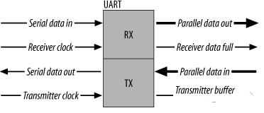
If a suitable level converter, such as SP3232E or SP3485, is added, UART can also be used for RS-232 and RS-485 communication, or connected to a computer’s port. UART is widely used in applications such as mobile phones, industrial control, and PCs.
UART uses asynchronous serial communication.
Serial communication refers to the transmission of data one bit at a time over a single transmission line. Its characteristics are simple communication lines, allowing communication with simple cables, reducing costs, suitable for long-distance communication, but applicable in scenarios where transmission speed is slow.
Asynchronous communication uses one character as the transmission unit, and the time interval between two characters during communication is not fixed; however, the time interval between two adjacent bits within the same character is fixed.
The data transmission rate is expressed in baud rate, i.e., the number of binary bits transmitted per second. For example, if the data transmission rate is 120 characters per second, and each character is 10 bits (1 start bit, 7 data bits, 1 parity bit, 1 stop bit), then the transmission baud rate is 10 × 120 = 1200 characters per second = 1200 baud.
The data communication format is as shown in the figure below:
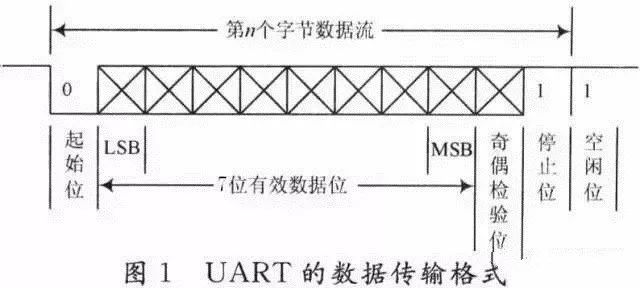
The meanings of each bit are as follows:
Start bit: A logical “0” signal is sent first, indicating the beginning of the transmitted character. Data bits: Can be 5 to 8 bits of logical “0” or “1”. For example, ASCII code (7 bits), extended BCD code (8 bits). LSB parity bit: After adding this bit to the data bits, the number of “1” bits should be even (even parity) or odd (odd parity). Stop bit: It is an end marker for a character data. It can be 1, 1.5, or 2 bits of high level. Idle bit: Remains in logical “1” state, indicating that there is no data transmission on the current line.
Note: Asynchronous communication is character-based; the receiving device can correctly receive data as long as it can remain synchronized with the sending device within the transmission time of one character after receiving the start signal. The arrival of the next character’s start bit recalibrates the synchronization (achieved by detecting the start bit to self-synchronize the clocks of the sender and receiver).

2. RS-232 Standard
RS-232 is a serial physical interface standard established by the Electronic Industry Association (EIA) in the United States. RS is an abbreviation for “Recommended Standard,” and 232 is the identification number. RS-232 specifies the electrical characteristics and physical characteristics, only affecting the data transmission path, and does not include how data is processed. It should be noted that many people often mistakenly refer to RS-232, RS-422, RS-485 as communication protocols, which is incorrect; they are merely mechanical and electrical interface standards concerning UART communication (at most, they are at the physical layer of network protocols).
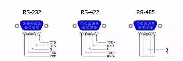
This standard specifies the use of a 25-pin DB-25 connector, regulating the signal content of each pin on the connector and the voltage levels of various signals. Later, IBM simplified RS-232 to the DB-9 connector, which became the de facto standard today. In industrial control, the RS-232 port generally only uses three lines: RXD (2), TXD (3), and GND (5).
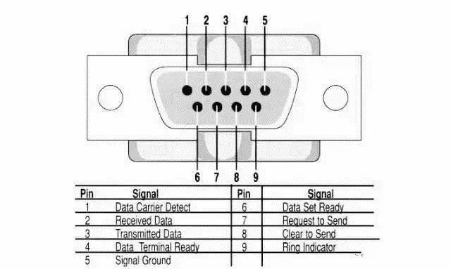
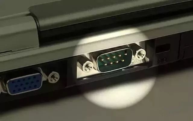
In the early days, since PCs all had RS-232 interfaces, we chose RS-232 when we needed to use UART. However, today, personal computers, including laptops and desktops, no longer have RS-232 interfaces; you may notice that there are no DB9 ports on computer motherboards. Therefore, development boards now typically use TTL UART or directly integrate UART to USB on the development board.
In embedded systems, the serial port usually refers to the UART port, but we often confuse it with the COM port and the relationships with RS232, TTL, etc. In fact, UART and COM refer to the physical interface form (hardware), while TTL and RS-232 refer to the voltage levels (electrical signals).
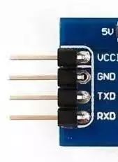
UART has 4 pins (VCC, GND, RX, TX), using TTL level, where low level is 0 (0V) and high level is 1 (3.3V or above).
3. RS-485/ RS-422 Standard
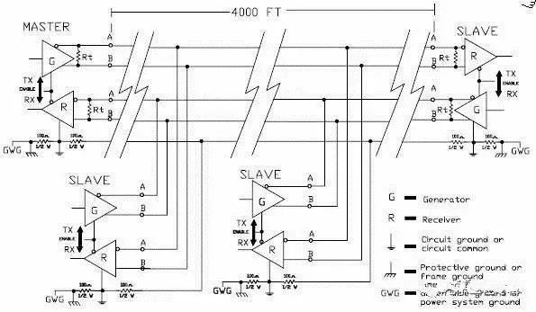
RS-232 interfaces can achieve point-to-point communication, but this method cannot realize networking. To solve this problem, a new standard, RS-485, was created. RS-485 data signals use differential transmission, also known as balanced transmission; it uses a pair of twisted wires, defining one wire as A and the other as B.
Under normal circumstances, the positive voltage level between sending drivers A and B is +2 to +6V, representing one logic state, and the negative voltage level is -2 to -6V, representing another logic state. There is also a signal ground C, and RS-485 has an “enable” terminal, which is optional in RS-422.
The electrical performance of RS-422 is exactly the same as that of RS-485. The main difference is that RS-422 has 4 signal lines: two for sending and two for receiving. Since RS-422’s receiving and sending are separate, it can receive and send simultaneously (full duplex). Because full duplex requires separate channels for sending and receiving, RS-422 is suitable for communication between two stations, star networks, and ring networks, but not for bus networks; RS-485 only has 2 signal lines, so it can only work in half-duplex mode, commonly used in bus networks.
1. The electrical characteristics of RS-485: Logic “1” is represented by the voltage difference of +(2~6)V between the two wires; Logic “0” is represented by the voltage difference of -(2~6)V between the two wires. The interface signal levels are lower than those of RS-232-C, making it less likely to damage the interface circuit chips, and this level is compatible with TTL levels, facilitating connections with TTL circuits.
2. The maximum data transmission rate of RS-485 is 10Mbps.
3. The RS-485 interface uses a combination of balanced drivers and differential receivers, enhancing the ability to resist common-mode interference, i.e., it has good noise resistance.
4. The maximum communication distance of RS-485 is about 1219M, with a maximum transmission rate of 10Mb/S; the transmission rate is inversely proportional to the transmission distance. At a transmission rate of 100Kb/S, the maximum communication distance can be achieved. If longer distances are needed, RS-485 repeaters must be added. The RS-485 bus generally supports a maximum of 32 nodes; if special RS-485 chips are used, it can reach 128 or 256 nodes, with a maximum of 400 nodes.
Due to the early emergence of the RS-232 interface standard, it inevitably has some shortcomings, mainly as follows:
(1) The signal voltage levels of the interface are relatively high, which can easily damage the interface circuit chips, and because the 232 level is not compatible with TTL levels, a level conversion circuit is required to connect with TTL circuits;
(2) The transmission rate is relatively low; in asynchronous transmission, the baud rate is 20Kbps. Now, due to the adoption of new UART chips, baud rates have reached 115.2Kbps (1.832M/16);
(3) The interface uses one signal line and one signal return line to form a common-ground transmission format, which is prone to common-mode interference, resulting in weak noise resistance;
(4) The transmission distance is limited, with a maximum standard transmission distance of 50 meters, but in practice, it can only be used at around 15 meters;
(5) RS-232 only allows point-to-point communication and does not consider forming a serial bus. (This point is very important; in many control scenarios, it is one control to many. If the master device needs to communicate with slave devices point-to-point, the on-site wiring becomes a spider web.)
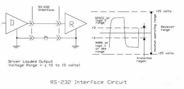
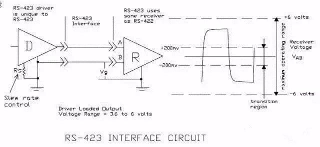
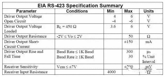
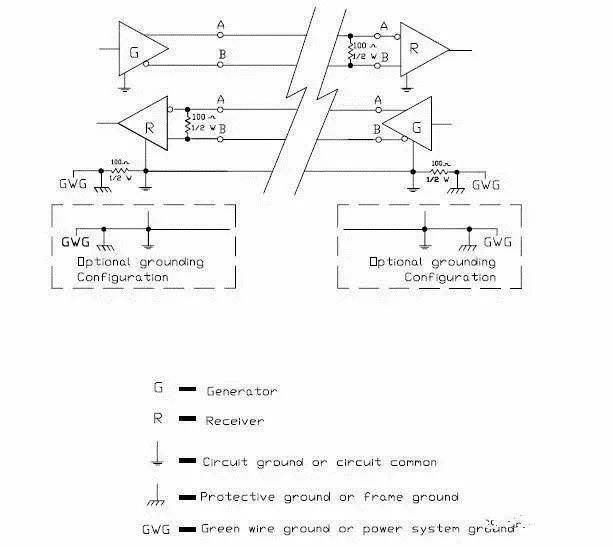
Unbalanced serial communication interfaces RS-423, RS-449
Balanced serial communication interface RS-422
RS-422 (EIA RS-422-A Standard) is the serial connection standard for Apple’s Macintosh computers. RS-422 uses differential signals, while RS-232 uses unbalanced reference ground signals. Differential transmission uses two wires to send and receive signals. Compared to RS-232, it has better noise resistance and longer transmission distances. In industrial environments, better noise resistance and longer transmission distances are significant advantages.
4. Comparison Between RS-232 and RS-485
1. Interference resistance: The RS-485 interface uses a combination of balanced drivers and differential receivers, offering good noise resistance. The RS-232 interface uses one signal line and one signal return line to form a common-ground transmission format, which is prone to common-mode interference.
2. Transmission distance: The maximum standard transmission distance of the RS-485 interface is 1200 meters (at 9600bps), and it can actually reach 3000 meters. RS-232 has a limited transmission distance, with a maximum standard transmission distance of 50 meters, practically usable at around 15 meters.
3. Communication capability: The RS-485 interface allows up to 128 transceivers on the bus, enabling users to easily establish device networks using a single RS-485 interface. RS-232 only allows point-to-point communication.
4. Transmission rate: RS-232 has a lower transmission rate, with a baud rate of 20Kbps in asynchronous transmission. RS-485 has a maximum data transmission rate of 10Mbps.
5. Signal lines: A half-duplex network formed by the RS-485 interface generally requires only two signal lines. The RS-232 interface generally only uses RXD, TXD, and GND three lines.
6. Electrical voltage levels: The logic “1” of RS-485 is represented by a voltage difference of + (2-6) V between the two wires; logic “0” is represented by a voltage difference of – (2-6) V. In RS-232-C, any signal line has a negative logic relationship. That is: logic “1” is -5 to -15V; logic “0” is +5 to +15V.
5. Comparison Between RS-422 and RS-485
The electrical performance of RS-485 is exactly the same as that of RS-422. The main differences are:
1. RS-422 has 4 signal lines: two for sending (Y, Z) and two for receiving (A, B). Since RS-422’s sending and receiving are separate, it can send and receive simultaneously (full duplex).
2. RS-485 only has two data lines: sending and receiving are both A and B. Since RS-485 shares the same two lines for sending and receiving, it cannot send and receive simultaneously (half duplex).
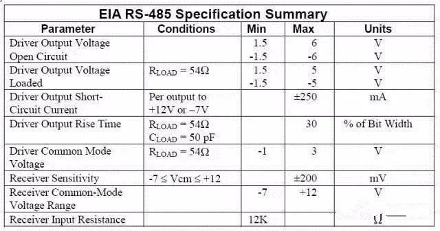
The RS-485 standard uses balanced sending and differential receiving data transceivers to drive the bus, with specific specifications required:
The input resistance of the receiver RIN ≥ 12kΩ
The driver can output a common-mode voltage of ±7V
The input capacitance ≤ 50pF
In the case of 32 nodes and a 120Ω termination resistor, the driver can still output at least 1.5V (the size of the termination resistor relates to the parameters of the twisted pair used).
The input sensitivity of the receiver is 200mV (i.e., (V+) – (V-) ≥ 0.2V, indicating signal “0”; (V+) – (V-) ≤ -0.2V, indicating signal “1”).
Due to the long distance, multi-node (32 nodes), and low transmission line costs of RS-485, EIA RS-485 has become the preferred standard for data transmission in industrial applications.
(1) RS-485’s electrical characteristics: The sending end: Logic “0” is represented by a voltage difference of + (2~6)V between the two wires; Logic “1” is represented by a voltage difference of – (2~6)V between the two wires. The receiving end: A is considered logic “0” if it is more than 200mV higher than B, and A is considered logic “1” if it is more than 200mV lower than B;
(2) The maximum data transmission rate of RS-485 is 10Mbps. However, since RS-485 often needs to communicate with the RS-232 port of a PC, the actual maximum is generally 115.2Kbps. Due to high rates reducing transmission distance, it is often around or below 9600bps;
(3) The RS-485 interface uses a combination of balanced drivers and differential receivers, offering good noise resistance;
(4) The maximum standard transmission distance of RS-485 is 1200 meters (at 9600bps), and it can actually reach 3000 meters. The RS-485 interface allows up to 128 transceivers on the bus, meaning RS-485 has multi-machine communication capabilities, allowing users to easily establish networks using a single RS-485 interface. Since the RS-485 interface forms a half-duplex network, it generally only requires two signal lines, so RS-485 interfaces use twisted pair transmission. The RS-485 international standard does not specify a connector standard for RS-485 interfaces, so terminal blocks or DB-9, DB-25 connectors can be used.
When using RS-485 interfaces, the maximum cable length allowed for data signal transmission from the generator to the load is a function of the data signal rate, which is mainly limited by signal distortion and noise. The maximum cable length and signal rate relationship is derived from using 24AWG copper twisted telephone cable (diameter 0.51mm), with inter-wire bypass capacitance of 52.5PF/M and terminal load resistance of 100 ohms. (Cited from GB11014-89 Appendix A). When the data signal rate is reduced to below 90Kbit/S, assuming the maximum allowable signal loss is 6dBV, the cable length is limited to 1200m. In practice, it is entirely possible to achieve greater cable lengths. Using cables of different diameters will result in different maximum cable lengths. For example, when the data signal rate is 600Kbit/S, using 24AWG cable, the maximum cable length is 200m; if using 19AWG cable (diameter 0.91mm), the cable length can exceed 200m; if using 28AWG cable (diameter 0.32mm), the cable length must be less than 200m.
For long-distance communication with RS-485, it is recommended to use shielded cables and connect the shielding layer to the ground.
6. Three Factors Affecting RS-485 Bus Communication Speed and Reliability
1. Signal Reflection in Communication Cables
During communication, two signal factors cause signal reflection: impedance discontinuity and impedance mismatch.
Impedance discontinuity causes signals to encounter very low or no cable impedance at the end of the transmission line, resulting in reflection at that point, as illustrated. This principle of signal reflection is similar to light reflecting when it enters another medium. To eliminate such reflections, a termination resistor matching the characteristic impedance of the cable must be bridged at the end of the cable to maintain impedance continuity. Since signals are transmitted bidirectionally on the cable, a similar termination resistor should be bridged at the other end of the communication cable.
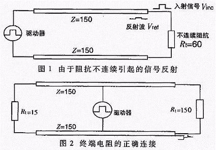
Theoretically, as long as a termination resistor matching the cable’s characteristic impedance is bridged at the end of the transmission cable, signal reflection should no longer occur. However, in practical applications, due to the characteristic impedance of the transmission cable and the communication baud rate, the characteristic impedance may not be exactly equal to the termination resistor, resulting in some signal reflections.
Another cause of signal reflection is the impedance mismatch between the data transceiver and the transmission cable. This causes reflections primarily when the communication line is idle, leading to data chaos in the entire network.
The impact of signal reflection on data transmission ultimately arises because the reflected signal triggers the comparator at the receiver’s input, causing it to receive incorrect signals, resulting in CRC check errors or entire data frame errors.
In signal analysis, the parameter used to measure the strength of reflected signals is RAF (Reflection Attenuation Factor). Its calculation formula is as follows:
RAF=20lg(Vref/Vinc) (1)
Where: Vref—voltage magnitude of the reflected signal; Vinc—voltage magnitude of the incident signal at the connection point of the cable and the transceiver or termination resistor.
The specific measurement method is shown in the figure. For example, if the peak-to-peak value of the incident signal sine wave at 2.5MHz is +5V, and the peak-to-peak value of the reflected signal is +0.297V, then the reflection attenuation factor of this communication cable at a communication rate of 2.5MHz is:
RAF=20lg(0.297/2.5)=-24.52dB
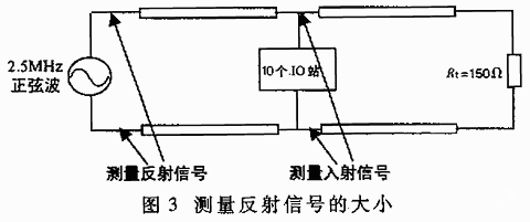
To mitigate the impact of reflected signals on communication lines, noise suppression and bias resistors are commonly used. In practical applications, for relatively small reflected signals, the method of adding bias resistors is often used for simplicity. The principle of how to improve communication reliability through bias resistors in communication lines.
2. Signal Attenuation in Communication Cables
The second factor affecting signal transmission is the attenuation of the signal during transmission through the cable. A transmission cable can be viewed as an equivalent circuit composed of distributed capacitance, distributed inductance, and resistance, as shown in the figure.
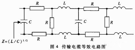
The distributed capacitance C of the cable is mainly generated by the two parallel conductors of the twisted pair. The resistance of the conductors has a minimal effect on the signal and can be ignored. Signal loss mainly occurs due to the LC low-pass filter formed by the distributed capacitance and distributed inductance of the cable. The attenuation coefficients of the LAN standard two-core cable (the standard cable selected by Siemens for DP bus) at different baud rates are shown in Table 1.
Attenuation coefficients of the cable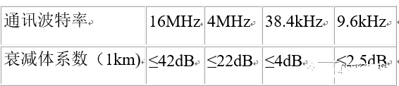
3. Pure Resistive Load in Communication Cables
The third factor affecting communication performance is the size of the pure resistive load (also known as DC load). The pure resistive load here mainly consists of termination resistors, bias resistors, and RS-485 transceivers.
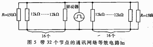
In discussing the EIA RS-485 specification, it was mentioned that RS-485 drivers can output at least 1.5V differential voltage with 32 nodes and 150Ω termination resistors. The input resistance of one receiver is 12kΩ, and the entire network’s equivalent circuit is shown in Figure 5. Based on this calculation, the load capacity of the RS-485 driver is:
RL=32 input resistors in parallel with 2 termination resistors=(((12000/32)×(150/2))/((12000/32)+(150/2)))≈51.7Ω
Currently, commonly used RS-485 drivers include MAX485, DS3695, MAX1488/1489, and the ones used by Holley Company, such as SN75176A/D, among which some RS-485 drivers can achieve a load capacity of 20Ω. Without considering many other factors, based on the relationship between driving capacity and load, the maximum number of nodes a driver can support will far exceed 32.
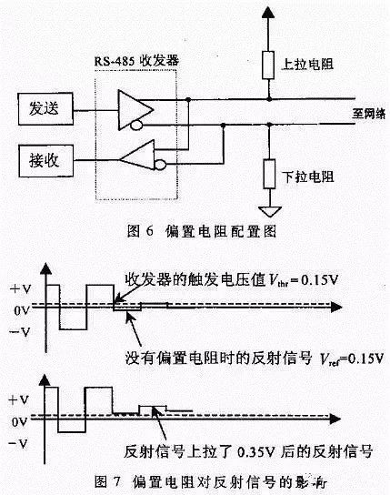
At higher communication baud rates, it is necessary to use bias resistors on the line. The connection method for bias resistors is shown in Figure 6. Their role is to pull the level on the bus away from 0V when the line enters idle state (idle mode), as shown in Figure 7. This way, even if small reflected signals or interference appear in the line, the data receivers connected to the bus will not malfunction due to these signals.
Through the following example, we can calculate the size of the bias resistors:
Termination resistors Rt1=Rr2=120Ω;
Assuming the maximum peak-to-peak value of the reflected signal Vref≤0.3Vp-p, then the negative half-cycle voltage Vref≤0.15V; the reflected current Iref caused by the reflected signal on the termination resistor ≤0.15/(120||120)=2.5mA. The hysteresis voltage value of the general RS-485 transceiver (including SN75176) is 50mV, that is:
(Ibias-Iref)×(Rt1||Rt2)≥50mV
Thus, we can calculate that the bias current produced by the bias resistors Ibias≥3.33mA
+5V=Ibias(Rup+Rdown+(Rt1||Rt2)) (2)
Using equation (2), we can calculate Rup=Rdown=720Ω
In practical applications, there are two methods for adding bias resistors to the RS-485 bus:
(1) Distributing the bias resistors evenly to each transceiver on the bus. This method adds bias resistors to each transceiver on the RS-485 bus, providing each transceiver with a bias voltage.
(2) Using a pair of bias resistors on a segment of the bus. This method is effective for large reflected signals or interference signals on the bus. It is worth noting that the addition of bias resistors increases the load on the bus.
7. The Relationship Between the Load Capacity of RS-485 Bus and the Length of Communication Cables
When designing the network configuration of the RS-485 bus (bus length and number of loads), three parameters should be considered: pure resistive load, signal attenuation, and noise margin. The pure resistive load and signal attenuation have been discussed earlier; now we will discuss the noise margin. The noise margin of the RS-485 bus receiver should be at least greater than 200mV. The previous discussions assumed a noise margin of 0. In practical applications, to enhance the bus’s anti-interference capability, it is always hoped that the system’s noise margin is better than what is specified in the EIA RS-485 standard. From the following formula, the relationship between the number of loads on the bus and the length of communication cables can be seen:
Vend=0.8(Vdriver-Vloss-Vnoise-Vbias)(3)
Where: Vend is the signal voltage at the end of the bus, which is specified to be 0.2V during standard measurement; Vdriver is the output voltage of the driver (related to the number of loads. If the number of loads is between 5 and 35, Vdriver=2.4V; if the number of loads is less than 5, Vdriver=2.5V; if the number of loads is greater than 35, Vdriver≤2.3V); Vloss is the signal loss during transmission in the bus (related to the specifications and length of communication cables), calculated from the standard cable’s attenuation coefficient provided in Table 1, according to the formula attenuation coefficient b=20lg(Vout/Vin), Vloss=Vin-Vout=0.6V (Note: The communication baud rate is 9.6kbps, and the cable length is 1km; if the baud rate increases, Vloss will also increase); Vnoise is the noise margin, which is specified to be 0.1V during standard measurement; Vbias is the bias voltage provided by the bias resistors (typical value is 0.4V).
The multiplication by 0.8 in equation (3) is to prevent the communication cable from entering a fully loaded state. From equation (3), it can be seen that the size of Vdriver is inversely proportional to the number of loads on the bus, and the size of Vloss is inversely proportional to the length of the bus; the other parameters are only related to the type of driver used. Therefore, once the RS-495 driver is selected, under a certain communication baud rate, the number of loads on the bus is directly related to the maximum distance that the signal can be transmitted. The specific relationship is: within the allowable range of the bus, the more loads there are, the shorter the distance the signal can transmit; the fewer loads there are, the farther the signal can transmit.
8. The Impact of Distributed Capacitance on RS-485 Bus Transmission Performance
The distributed capacitance of the cable is mainly generated by the two parallel conductors of the twisted pair. Additionally, there is distributed capacitance between the conductors and the ground, which is small but cannot be ignored in analysis. The impact of distributed capacitance on bus transmission performance mainly arises because the signal transmitted on the bus is a fundamental wave signal, expressed only as “1” and “0”. In special bytes, for example, 0x01, the signal “0” allows sufficient charging time for the distributed capacitance, while when the signal “1” arrives, the charge in the distributed capacitance may not discharge in time, resulting in (Vin+) – (Vin-) being greater than 200mV, causing the receiver to mistakenly identify it as “0,” ultimately leading to CRC check errors and incorrect transmission of the entire data frame. The specific process is illustrated in the figure.
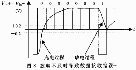
The impact of distributed effects on the bus leads to data transmission errors, thereby reducing the overall network performance. To solve this problem, two methods are available:
(1) Reducing the baud rate of data transmission;
(2) Using cables with lower distributed capacitance to improve the quality of the transmission line.
Simply connecting the A and B ends of each interface with a pair of twisted wires without grounding the RS-485 communication link can work in some cases, but it poses hidden dangers for the system. The RS-485 interface uses differential transmission to transmit signals without needing a reference point to detect the signal system; it only needs to detect the voltage difference between the two wires. However, it should be noted that the transceiver can only operate normally when the common-mode voltage does not exceed a certain range (-7V to +12V). When the common-mode voltage exceeds this range, it affects the reliability of communication and may even damage the interface. As shown in the figure, when transmitter A sends data to receiver B, the output common-mode voltage of transmitter A is VOS, and due to the existence of a ground potential difference VGPD between the two systems having their own independent grounding systems, the common-mode voltage at the receiver input can reach VCM=VOS+VGPD. The RS-485 standard specifies that VOS≤3V, but VGPD can have a large amplitude (tens of volts or even dozens of volts), and may be accompanied by strong interference signals, causing the common-mode input VCM of the receiver to exceed the normal range, generating interference currents on the signal line that affect normal communication or damage the equipment.
Conclusion:
The serial port is a very versatile device interface, commonly used for communication in instruments and equipment, often utilized for remotely collecting device data or achieving remote control. The development of serial ports is relatively simple, making them one of the favorite interfaces for many engineers.

Your likes are the motivation for the editor