Follow + Star our official account to not miss exciting content

Author | A Person and a Team
Official WeChat Account | A Person and a Team
According to technical specifications and electrical interfaces, there are three common serial data standards: RS-232, RS-422, and RS-485. This article will introduce cable termination techniques, the use of multiple loads, RS-232 daisy chain connections, conversion from RS-232 to RS-485, conversion from RS-485 to RS-232, and powering RS-485 conversion from the RS-232 port.
Introduction
The wonder of standards lies in the multitude of choices available, which also applies to electrical interface standards. With the independent development of serial data standards across different industries, we have never had so many standards available.
The most successful serial data standard in the PC and telecommunications application fields is likely RS-232. Similarly, RS-485 and RS-422 are also among the most successful standards in industrial applications. These standards are not directly compatible. However, for control and instrumentation applications, communication often must occur between different standards. This article discusses the different standards (physical layer specifications), explains how to convert from one standard to another, and demonstrates how to combine different standards in the same application.
RS-232 Electrical Specifications and Typical Connections
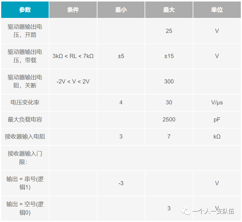
The RS-232 link was originally used to support modems and printers on IBM PCs. However, this standard now supports various peripherals communicating with PCs. The RS-232 standard is defined as a single-ended standard used to enhance serial communication distance at lower baud rates (<20 kbps). Over the years, this standard has undergone several changes to support faster drivers, such as the MAX3225E, which can provide a data transmission rate of 1 Mbps. To be compatible with RS-232, transceivers like the MAX3225E must meet the electrical specifications listed in Table 1. From the typical connection (Figure 1), it can be seen that hardware handshaking is used to control data flow.
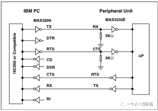
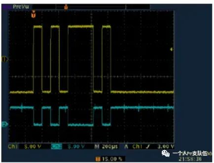
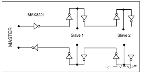
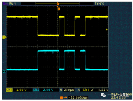
The typical signal swing of RS-232 (Figure 2, CH1) ranges from positive to negative. Note the relative position of the 0V trace mark on the left coordinate axis. Although RS-232 data is inverted, the conversion from TTL/CMOS to RS-232 and back to TTL/CMOS restores the original polarity of the data. The typical transmission distance for RS-232 rarely exceeds 100 feet. There are two reasons for this: first, the difference between the transmission level (±5V) and the receiving level (±3V) only allows for 2V of common-mode rejection; second, the distributed capacitance of longer cables may exceed the specified maximum load (2500pF), thus reducing the slew rate. Since RS-232 is designed as a point-to-point interface, not a multi-node interface, its driver specifications are for a single load of 3kΩ to 7kΩ. Therefore, multi-node interface applications typically use a daisy chain connection method (Figure 3).
Daisy Chain Devices and Their Limitations
In a daisy chain configuration, RS-232 signals pass through the first receiver and loop back to the transmitter. This configuration is repeated for devices further along the data sending line. The main issue with this technique is cable breaks. If a break occurs between Slave 1 and Slave 2, it prevents all downstream devices from sending or receiving data. Another multi-node RS-232 technique involves pre-buffering or RS-232 output boosting (to drive multiple parallel 5kΩ inputs).
To avoid issues related to daisy chain networks, ADI developed the MAX3322E/MAX3323E, specifically designed for multi-node applications. These unique devices feature a 5kΩ logic switch input resistance. When the device is not selected, its input resistance remains in a high-impedance state, allowing communication to continue with other devices on the shared bus.
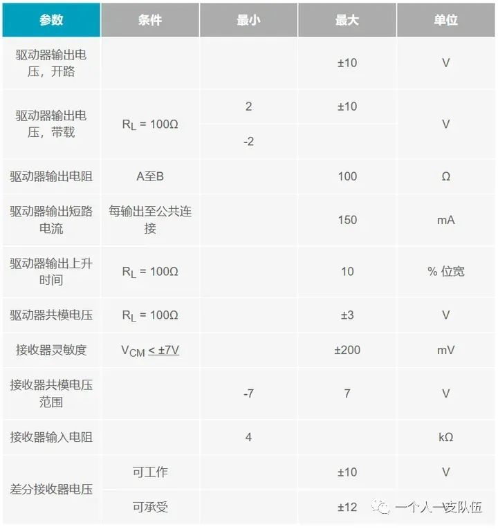
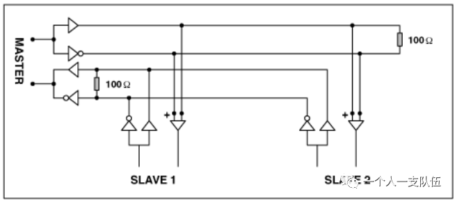
Another solution to daisy chain network issues is to convert RS-232 Rx and Tx signals to RS-422 signals (see Table 2). RS-422 is a differential standard that allows for much longer transmission distances. RS-422’s higher input impedance, combined with its higher driving capability, allows for the connection of up to 10 nodes (Figure 4). Another advantage of RS-422 is its independent transmit and receive pathways, which do not require direction control. Handshaking between devices can be implemented using software (XON/OFF handshaking) or hardware (a pair of separate twisted pairs). The MAX3162 provides an economical way to convert signals between RS-232 and RS-422. For more information, refer to the RS-232/RS-485 protocol converter section below.
Differences Between RS-485 and RS-422 and Their Usage in Reapplications
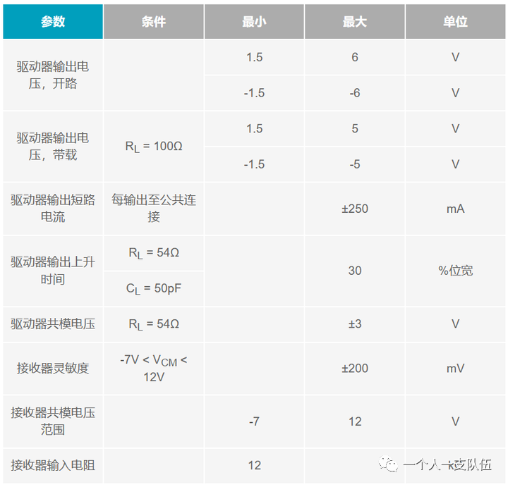
RS-422 and RS-485 transceivers are often confused, with one being mistaken for the full-duplex version of the other. However, the electrical differences in common-mode range and receiver input resistance make these standards suitable for different applications. Since RS-485 meets all RS-422 specifications (Table 3), RS-485 drivers can be used in RS-422 applications. However, the reverse is not true. The common-mode output of RS-485 drivers ranges from -7V to +12V, while the common-mode range for RS-422 is only ±3V. The minimum receiver input resistance for RS-422 drivers is 4kΩ, whereas for RS-485 drivers, it is 12kΩ.
To reduce wiring costs and achieve longer line lengths, RS-485 transceivers have become a widely adopted standard in sales terminals, industrial, and telecommunications applications. The wider common-mode range of RS-485 also supports longer line lengths and higher input resistance per node, allowing more nodes to be connected on the bus (Figure 5).
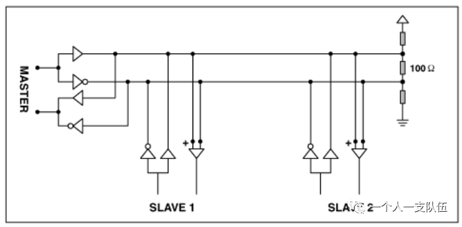
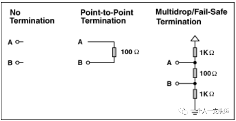
Differential RS-485 transmission (Figure 6) creates opposite currents and magnetic fields on each line of a twisted pair cable, canceling out the reverse magnetic fields around each wire, thereby minimizing radiated electromagnetic interference (EMI). To transmit over longer cables or at higher data rates, the cable acts as a transmission line and should be terminated using the cable’s characteristic impedance. This aspect of RS-485 connections can be confusing. Does the transmission line need to be terminated? If so, how should it be terminated? If the designer is not the end user, should these questions be left to the installers to resolve? For most RS-485 transceivers, the data sheet indicates a simple choice between non-termination and simple point-to-point termination when the cable acts as a transmission line (Figure 7). Termination resistors between the A-B terminals are harmless. By default, termination should be applied at the last transceiver on the bus.
Failure Protection
Determining whether termination resistors are needed is just one of the issues faced when implementing an RS-485 system. Normally, if A is greater than B by +200mV or more, the RS-485 receiver outputs a “1”; if B is greater than A by 200mV or more, the transceiver outputs a “0”. In a half-duplex RS-485 network, the host transceiver places the bus in a tri-state after sending a message to the slave. Therefore, if there is no signal driving the bus, the output state of the receiver is undefined, as the difference between A and B approaches 0V. If the receiver output RO is “0”, the slave interprets it as a new start bit and attempts to read the subsequent byte. Since there will be no stop bit, the result is a framing error. The bus becomes masterless, causing the network to stall.
Unfortunately, for 0V differential inputs, different chip tests may produce different output signals. Prototypes may work normally, but specific nodes may fail during production testing. To address this issue, as shown in Figure 7 with multi-node/failure protection termination, a bias is applied to the bus. Biasing the bus ensures that the receiver output remains “1” when the bus is in a tri-state. Alternatively, you could use “true failure protection” receivers, such as MAX3080 (5V) and MAX3070 (3V) series products. These devices change the threshold of the receiver to -50mV, ensuring that the RO output is “1” when the differential input is 0V.
RS-232/RS-485 Protocol Converters
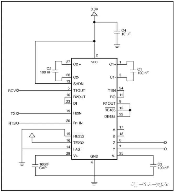
The MAX3162 is a unique device that includes both RS-232 and RS-485 receivers and transmitters. This wide-range communication device is integrated into a single chip, supporting bidirectional independent conversion between RS-232 and RS-485 signals. The circuit shown in Figure 8 configures the MAX3162 for bidirectional conversion of RS-232 and RS-485 signals in point-to-point applications.
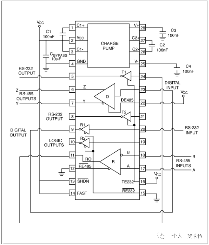
Figure 9 shows the MAX3162 configured as an RS-232/RS-485 multi-node protocol converter. The conversion direction is controlled by the RTS signal R1IN. The single-ended RS-232 receiver input signal is converted to a differential RS-485 transmitter output; similarly, the differential RS-485 receiver input signal is converted to a single-ended RS-232 transmitter output. The RS-232 data received on R2IN is sent as RS-485 signals on Z and Y; the RS-485 signals received on A and B are sent as RS-232 signals on T1OUT.
The RTS line is a shared line used to control the direction of the bus for converting between RS-232 and RS-485. This line controls whether the RS-485 transceiver acts as a transmitter or receiver at the RS-232 port (Figure 9). Note that the system is uncertain whether the data byte in the UART transmission buffer has been sent unless the system monitors the input DI of the RS-485 driver. That is, the system must allow for a fixed delay or actively monitor the DI input before using the DE input to change the bus direction.
Other direction control techniques include using a microcontroller and utilizing data-driven DE inputs while polling the voltage difference across the A-B lines (using a pull-up resistor to connect A to 5V and a pull-down resistor to connect B to ground). The values of these resistors may vary with cable capacitance, but typical values are 1kΩ.
Port-Powered Devices
Many RS-232 to RS-485 converters are “port-powered converters,” which provide power to RS-485 through the RS-232 RTS line (or sometimes a combination of RTS and CTS (DTR) lines). Due to the limited power available from RS-232 ports, when a port-powered converter is used with, for example, 100 RS-485 endpoints, it may not reach the startup voltage for RS-485. However, the lower receiver threshold (200mV) allows for better margin of error. This technique is widely used in systems with shorter lines and where there are no termination resistors between A and B endpoints.
Hot Plugging
Inserting a circuit board into a working or powered backplane can cause differential interference on the data bus, leading to data errors. When inserting a circuit board, the data communication processor first enters its power-up sequence. During this period, the processor logic output driver is in a high-impedance state and cannot drive the DE and/RE inputs of the MAX3060E/MAX3080E to the specified logic levels. The leakage current when the processor logic driver is in a high-impedance state can be as high as ±10mA, which may cause the standard CMOS enable input of the transceiver to drift, resulting in an incorrect logic level. Furthermore, parasitic capacitance on the circuit board may couple VCC or GND to the enable input. If hot plugging is not supported, these factors may erroneously enable the transceiver’s driver or receiver.
END
Previous Recommendations
CAN Bus
Working Principle of Inductors
Detailed Explanation of IIC Knowledge
Article Classification Directory Collection
Follow our official account and reply “Join Group” to join the technical exchange group according to the rules, reply “1024” to see more content.

Click the blue text to follow us