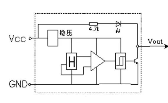
The potential difference generated by the Hall effect is very small, often only a few microvolts. Therefore, Hall sensors often have a built-in high-gain operational amplifier and may be combined with other system circuits based on overall requirements. The overall architecture is shown below.
Typically, the final output signals from Hall sensors can be either analog or digital.
Output digital signal: Generally, a Schmitt trigger is added after the operational amplifier stage, resulting in an output signal that is a digital signal, usually providing the corresponding hysteresis and switching threshold for the system, similar to a switch-type Hall device.
Output analog signal: The output of a linear Hall sensor is an analog signal, which can be sampled with an ADC to detect the displacement of an object.
Working Principle of Hall Switch
1. Introduction to the Principle
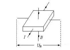
When a metal or semiconductor thin sheet carrying current is placed vertically in a magnetic field, a potential difference will be generated across the two ends of the sheet, a phenomenon known as the Hall effect. The potential difference across the ends is called the Hall potential U, expressed as:U=K·I·B/d, where K is the Hall coefficient, I is the current passing through the sheet, B is the magnetic induction intensity of the external magnetic field (Lorentz force), and d is the thickness of the sheet.From this, it can be seen that the sensitivity of the Hall effect is directly proportional to the magnetic induction intensity of the external magnetic field.
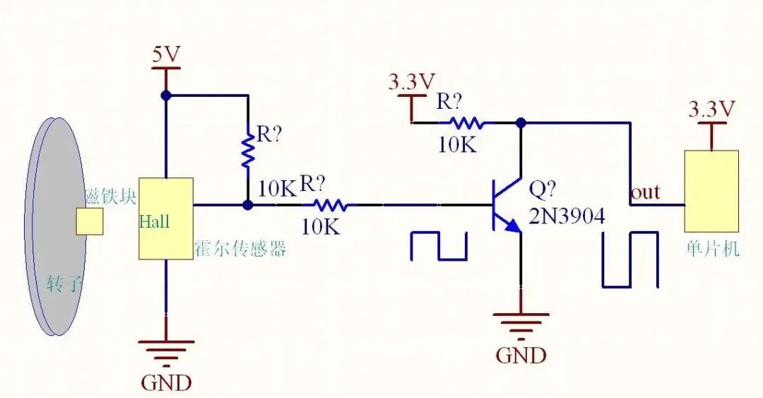
A Hall switch is a type of active magnetic-electric conversion device that is based on the principle of the Hall effect, made using integrated packaging and assembly processes. It conveniently converts magnetic input signals into actual application electrical signals. The input of the Hall switch is characterized by the magnetic induction intensity B; when the B value reaches a certain level (e.g., B1), the trigger inside the Hall switch flips, and the output level state of the Hall switch also flips. The output is generally through a transistor, similar to proximity switches, which can be NPN, PNP, normally open, normally closed, latching (bipolar), or dual signal output types.
2. Internal Schematic

Four Leakage Current Meanings
In the case where the machine’s main switch is off, the leakage current consumption of the charging circuit connected to the battery: the leakage current between the machine and the battery;
Power consumption when BMS supplies power to the battery: the power consumption of the battery for the battery protection board itself;
Power consumption when BMS shuts off power to the PCBA: the leakage consumption of the battery after entering the protection state for the external protection board and machine;
Self-discharge power consumption of the battery cell: the self-leakage loss of the battery cell;
Role of Filtering Capacitors in EMC Design Circuits
In practical engineering, the electromagnetic noise frequency to be filtered often reaches hundreds of MHz, even exceeding 1 GHz. To effectively filter such high-frequency electromagnetic noise, a through-hole capacitor must be used.The reason ordinary capacitors cannot effectively filter high-frequency noise is due to two reasons:One reason is that the lead inductance of the capacitor causes resonance, presenting a large impedance to high-frequency signals, weakening the bypass effect on high-frequency signals;The other reason is that parasitic capacitance between wires causes high-frequency signals to couple, reducing filtering effectiveness.
The reason through-hole capacitors can effectively filter high-frequency noise is that they do not have the problem of low resonance frequency caused by lead inductance, and they can be directly mounted on metal panels, using the metal panel for high-frequency isolation. However, when using through-hole capacitors, attention must be paid to installation issues.
The greatest weakness of through-hole capacitors is their sensitivity to high temperatures and thermal shock, which poses significant challenges when soldering them to metal panels. Many capacitors can be damaged during the soldering process. Especially when a large number of through-hole capacitors need to be installed on a panel, if one is damaged, it is difficult to repair because removing the damaged capacitor can cause damage to neighboring capacitors.
Role of Common Mode Inductors in EMC Design Circuits
Since the problems faced by EMC are mostly common mode interference, common mode inductors are also one of our commonly used powerful components. A common mode inductor is a common mode interference suppression device with a ferrite core, consisting of two identical coils wound symmetrically on the same ferrite ring core, forming a four-terminal device that presents a large inductance for common mode signals while having a very small leakage inductance for differential mode signals, making it almost ineffective.
The principle is that when the common mode current flows, the magnetic flux in the magnetic ring adds up, resulting in a considerable inductance, which suppresses the common mode current. When the two coils carry differential mode current, the magnetic flux cancels each other out in the magnetic ring, resulting in almost no inductance, allowing the differential mode current to pass through without attenuation. Therefore, common mode inductors can effectively suppress common mode interference signals in balanced lines while having no impact on the normal transmission of differential mode signals.
Common mode inductors should meet the following requirements during production:
(1) The wire wound on the coil core must be insulated from each other to ensure that there is no breakdown short circuit between the turns under instantaneous over-voltage.
(2) When the coil carries instantaneous large currents, the core should not saturate.
(3) The core should be insulated from the coil to prevent breakdown between them under instantaneous over-voltage.
(4) The coil should be wound in a single layer as much as possible to reduce the parasitic capacitance of the coil and enhance the coil’s capability against instantaneous over-voltage.
Generally speaking, attention should be paid to selecting the required filtering frequency band, the greater the common mode impedance, the better. Therefore, when selecting common mode inductors, we need to refer to the component data, mainly based on the impedance frequency curve for selection. Additionally, consider the impact of differential mode impedance on the signal, especially for high-speed ports.
Role of Ferrite Beads in EMC Design Circuits
During the EMC design process of digital circuits in products, we often use ferrite beads. Ferrite materials are iron-magnesium alloys or iron-nickel alloys, which have a very high permeability and can produce minimal capacitance between the windings of inductors under high-frequency high-resistance conditions.
Ferrite materials are usually applied at high frequencies because at low frequencies they mainly exhibit inductive characteristics, resulting in low losses on the line. At high frequencies, they mainly exhibit capacitive characteristics and change with frequency. In practical applications, ferrite materials are used as high-frequency attenuators in radio frequency circuits.
In fact, ferrite is effectively equivalent to a parallel combination of resistance and inductance. At low frequencies, the resistance is shorted by the inductance, while at high frequencies, the inductive impedance becomes very high, causing all the current to pass through the resistance. Ferrite is a dissipative device, converting high-frequency energy into heat energy, which is determined by its resistive characteristics.
Ferrite beads have better high-frequency filtering characteristics compared to ordinary inductors. Ferrite exhibits resistive characteristics at high frequencies, equivalent to inductors with low quality factors, thus maintaining high impedance across a wide frequency range, improving high-frequency filtering efficiency.
At low frequencies, the impedance consists of the inductive reactance, and at low frequencies R is very small, with the magnetic permeability of the core being high, resulting in a large inductance, where L plays a major role, reflecting and suppressing electromagnetic interference; and at this time, the core loss is small, making the entire device a low-loss, high-Q characteristic inductor. This type of inductor can easily resonate, so sometimes using ferrite beads at low frequencies may enhance interference.
At high frequencies, the impedance consists of resistive components. As the frequency increases, the magnetic permeability of the core decreases, leading to a reduction in the inductance value and inductive reactance. However, the core loss increases, and the resistive component increases, leading to an overall increase in impedance. When high-frequency signals pass through ferrite, electromagnetic interference is absorbed and dissipated as heat.
Ferrite suppression components are widely used in printed circuit boards, power lines, and data lines. For example, adding ferrite suppression components at the power line entry of printed boards can filter out high-frequency interference. Ferrite rings or beads are specially used to suppress high-frequency interference and spikes on signal lines and power lines, and they also have the ability to absorb electrostatic discharge pulse interference.
Whether to use chip ferrite beads or chip inductors mainly depends on the actual application scenario. Chip inductors are needed in resonant circuits, while chip ferrite beads are the best choice for eliminating unwanted EMI noise.
Applications of Chip Ferrite Beads and Chip Inductors
Chip inductors: RF and wireless communication, information technology devices, radar detectors, automotive electronics, cellular phones, pagers, audio equipment, personal digital assistants (PDAs), wireless remote control systems, and low-voltage power supply modules, etc.
Chip ferrite beads: clock generation circuits, filtering between analog and digital circuits, I/O internal connectors (such as serial ports, parallel ports, keyboards, mice, long-distance telecommunications, local area networks), filtering high-frequency conducted interference in power circuits, and EMI noise suppression in computers, printers, video recorders (VCRs), television systems, and mobile phones.
The unit of ferrite beads is ohms, as the unit is named according to the impedance it generates at a certain frequency, and the unit of impedance is also ohms. The datasheet for ferrite beads usually provides frequency and impedance characteristic curves, generally with 100 MHz as the standard. For example, at a frequency of 100 MHz, the impedance of a ferrite bead is equivalent to 1000 ohms. For the frequency band we want to filter, it is best to choose ferrite beads with an impedance greater than 600 ohms.
Additionally, when selecting ferrite beads, attention should be paid to the current rating, generally requiring a derating of 80%, and when used in power circuits, the impact of DC resistance on voltage drop should be considered.
(Image source from the internet)
Click the mini program below for more repair cases