19.2
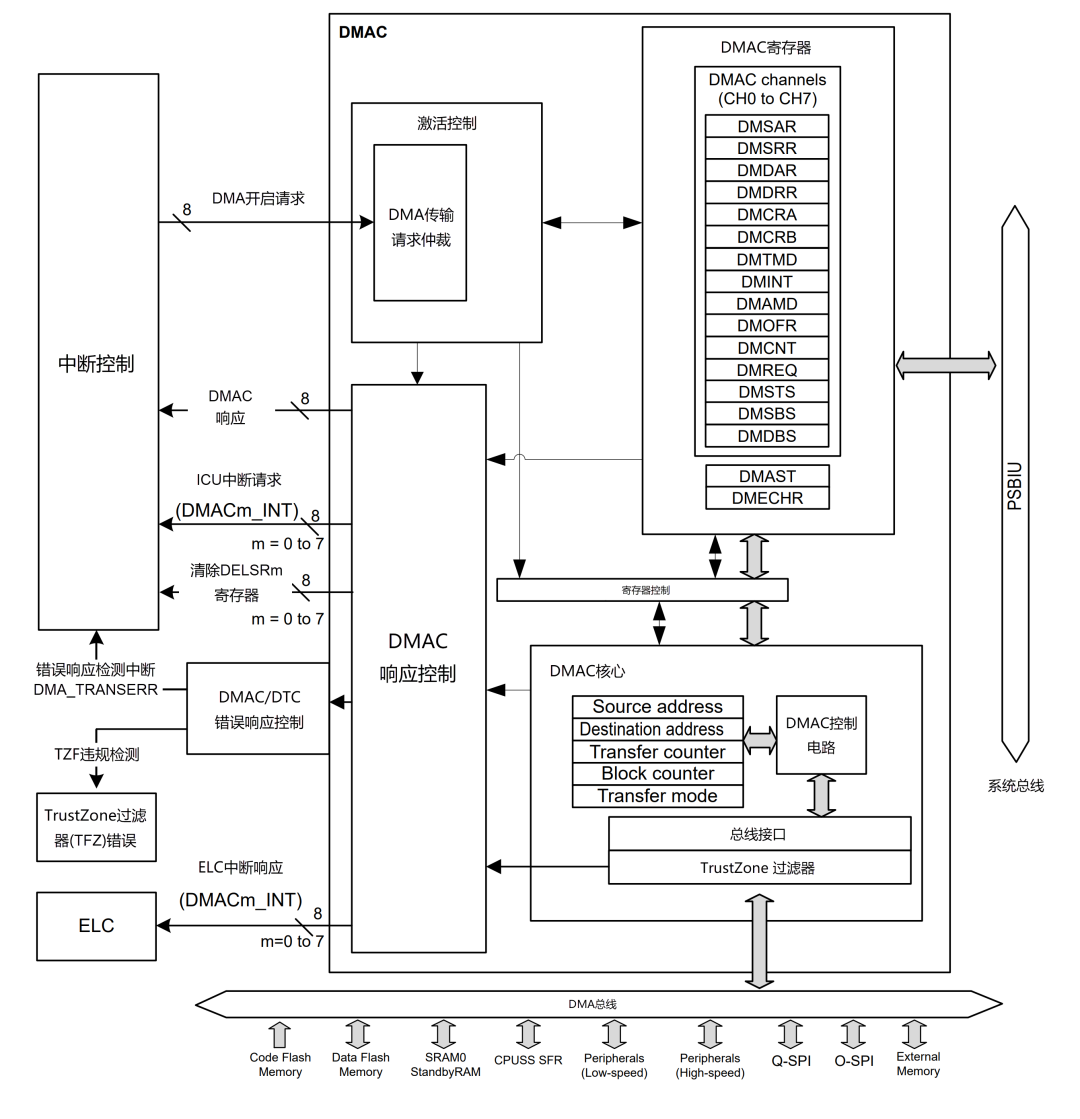
Analysis of DMAC Module Block Diagram
19.2.1
DMAC Activation Sources
Software triggers, interrupt requests from peripheral modules, and external interrupt requests can all be designated as DMAC activation sources. The DMAC activation source is set in the DMTMD register’s DCTG[1:0] bits.
19.2.1.1
Activating DMAC via Software
We can choose to initiate DMA transfers via software, meaning that the DMAC is activated manually for transfers without using interrupt requests from on-chip peripheral modules or external interrupts.
19.2.1.2
Activating DMAC via Interrupt Requests from On-Chip Peripheral Modules or External Interrupts
In addition to manually activating the DMAC via software, the DMAC can also be activated through interrupt requests from on-chip peripheral modules or external interrupts.
We can set the interrupt requests from on-chip peripheral modules and external interrupt requests as activation sources for the DMAC. The activation source for each channel can be individually selected through the DELSRn register’s DELS[8:0] bits (n=0~7) in the ICU.
19.2.2
Interrupt Priority
When multiple DMA transfer requests exist, the DMAC determines the priority of the channels with DMA transfer requests. The channel priority is fixed as follows: Channel 0 > Channel 1 > Channel 2 > Channel 3… > Channel 7 (Channel 0 has the highest priority).
When a DMA transfer request is generated during data transfer, channel arbitration begins after the final data has been transferred, and the DMA transfer of the channel with the higher priority starts.
19.2.3
Event Linking
Each DMAC channel outputs an event link request signal (DMACn_INT) upon completion of data transfer or block transfer mode. When the transfer destination is an external bus, an event link request signal is generated when the write buffer operation is accepted. For more details, refer to the Event Link Controller (ELC) section. If a bus error occurs during the last data of the write transfer, a transfer end event and error response detection interrupt (DMA_TRANSERR) will occur.
19.3
DMAC Transfer Modes
There are four DMAC transfer modes:
-
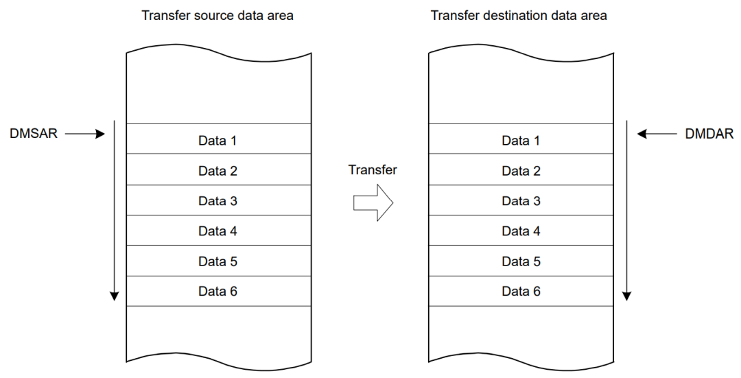
Normal Mode: In normal mode, the DMAC channel transfers a single data unit each time it receives a configured activation source. The data unit can be 1 byte, 2 bytes, or 4 bytes. After each transfer, the source and destination addresses can be fixed, incremented, decremented, or offset to the next data unit. A 16-bit counter decrements after each transfer. When the counter reaches 0, the transfer will no longer be triggered by the activation source, and a signal indicating that all transfers are complete can interrupt the CPU.
-
Repeat Mode: The repeat mode operates similarly to normal mode, but the length is limited to integers within the range [1, 1024]. When the transfer counter reaches 0, the counter is reset to its configured value, the repeat area (source or destination address) is reset to its starting address, and the remaining block count decrements by 1. When the block count reaches 0, the transfer will no longer be triggered by the activation source, and a configurable transfer complete interrupt can be generated.
-
Block Mode: In block mode, the amount of data units transferred per interrupt can be set to integers within the range [1, 1024]. The number of blocks to be transferred can also be configured as a 16-bit number. After each block transfer, the repeat area (source or destination address) will reset to the original address, while the other address increments or decrements to the next block.
-
Repeat-Block Mode: In repeat-block mode, the amount of data units transferred per interrupt can be set to integers within the range [1, 1024]. The number of blocks to be transferred can be configured as a 16-bit number (with a maximum repeat size of 64K, i.e., 65536).
If the destination address mode is offset mode, the maximum configurable block size for data transfer size in bytes is 0xFFFF, for half-word data transfer size is 0x7FFF, and for word data transfer size is 0x3FFF. After each block transfer, the source and destination addresses will increment or decrement to the next block address.
For the source address in offset mode, the source address size is the total size of the source buffer, after which the source area is flipped, and the block size can be less than the source buffer size. For the source address mode as offset mode, the maximum configurable source buffer size is 0xFFFF for byte transfer data size, 0x7FFF for half-word transfer data size, and 0x3FFF for word transfer data size.
Using repeat-block mode allows for the design of transfer types from single circular buffers to multiple circular buffers.
19.3.1
Normal Transfer Mode
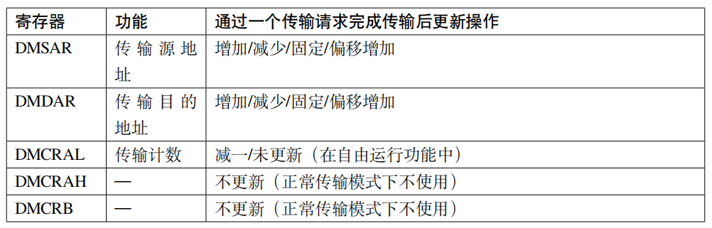
In normal transfer mode, a transfer request transfers one data. The maximum of 65535 can be set for the number of transfer operations using the DMCRAL register. When these bits are set to 0x0000, no specific number of transfer operations is set; data transfer is executed under the condition that the transfer counter stops (free-running function). In normal transfer mode, setting the DMCRB register is invalid. Apart from the free-running function, a transfer end interrupt request can be generated after completing the specified number of transfer operations.
Table 1: Register Update Operations in Normal Transfer Mode
19.3.2
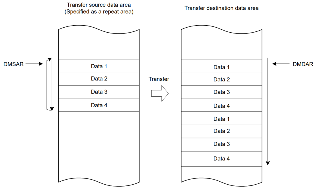
Repeat Transfer Mode
In repeat transfer mode, a single transfer request initiates the transfer of one data.
By setting the DMCRA register, a maximum of 1K data can be set as the total repeat transfer size; by setting the DMCRB register, a maximum of 64K can be set as the number of repeat transfer operations.
Thus, we can set a maximum of 64M data (1K data × 64K repeat transfer operation count) as the total data transfer size.
The transfer source address or transfer destination address can be set as the repeat area. When the transfer of the specified repeat size data is completed, the DMAC will reset the address of the repeat area to the transfer start address, creating a loop process.
After completing the specified number of repeat transfer operations, a transfer complete interrupt can be generated; an interrupt can be generated after each completion of a loop process.
By setting the DMCNT register’s DTE bit to 1, DMA transfer can be resumed.
After completing the specified number of repeat transfer operations, a transfer end interrupt request can be generated.
19.3.3
Block Transfer Mode
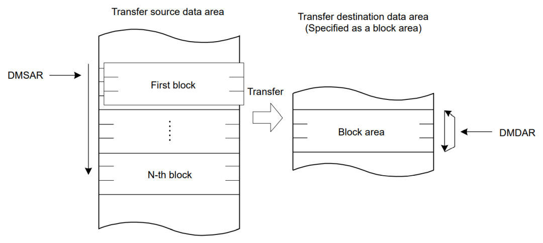
In block transfer mode, a single block of data is transferred through a transfer request.
Using the DMCRA register, a maximum of 1K data can be set as the total block transfer size.
Using the DMCRB register, a maximum of 64K can be set as the number of block transfer operations; thus, a maximum of 64M data (1K data × 64K block transfer operation count) can be set as the total data transfer size.
The transfer source or transfer destination can be specified as the block area. When the transfer of a single block of data is completed, the address of the specified block area (DMSAR or DMDAR) returns to the transfer start address. When all data of a single block is completely transferred in block transfer mode, DMA transfer can be stopped, and a repeat size end interrupt can be requested. By writing 1 to the DMCNT.DTE bit in the repeat size end interrupt handling, DMA transfer can be resumed.
Transfer end interrupt requests can be generated after completing the specified number of block transfer operations.
19.3.4
Repeat-Block Transfer Mode
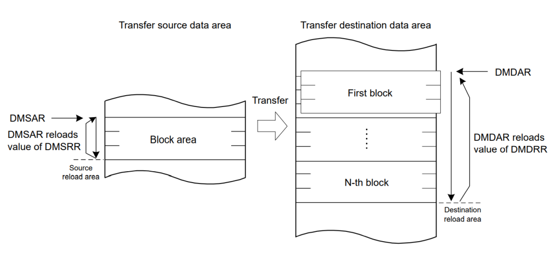
Repeat-block transfer mode (Repeat-Block Transfer Mode) mainly adds some functions based on block mode:
-
Repeat Function: Adds functionality (circular buffer) to repeat the specified address area.
-
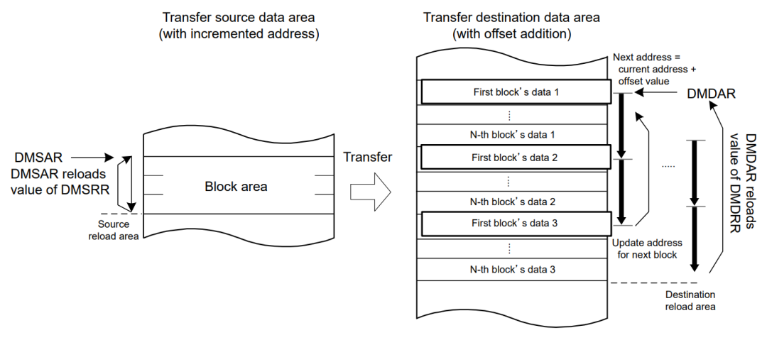
Offset Function: Allows specifying multiple areas with offsets in a single block transfer.
The repeat function and offset function can be used for the transfer source and transfer destination of repeat block transfers.
In repeat-block transfer mode, a single block of data is transferred through a transfer request.
Using DMACn’s DMCRA, a maximum of 1K data can be set as the total block transfer size. Using DMACn’s DMCRB, the number of block transfer operations can be set to a maximum of 64K; thus, a maximum of 64M data (1K data × 64K block transfer operation count) can be set as the total data transfer size.
The following figure is an example in repeat-block transfer mode
The following figure is an example in repeat-block transfer mode with offset increments

Need Technical Support?
If you have any questions while using Renesas MCU/MPU products, you can identify the QR code below or copy the URL into your browser to access the Renesas Technical Forum for answers or to obtain online technical support.

https://community-ja.renesas.com/zh/forums-groups/mcu-mpu/
To be continued
Recommended Reading

DMAC/DTC: Direct Memory Access and Data Transfer – Practical Guide to Renesas RA Series FSP Library Development (51)
UART Redirection in Version 5.2.0 E2S – Practical Guide to Renesas RA Series FSP Library Development (50)

Experiment 3: UART Echo Based on Circular Queue – Practical Guide to Renesas RA Series FSP Library Development (49)