▲Clickthe blue text“Schlumberger Digital and Integrated Group” to set as【Star】, to view information without getting “lost”.
In the first part, we introduced the work related to model preparation. This part discusses how to define the model.
After completing data collection, to ensure reliable results in asphaltene calculations, you need to correctly select and set the appropriate asphaltene model based on the problem you are addressing. Additionally, you should utilize all available experimental data to accurately calibrate the fluid.
Generally, you do not need to manually specify the asphaltene model; you can simply click the “Asphaltenes Model” button in the “Asphaltenes” toolbar to configure the software’s preset model (Figure 1).

Figure1. Asphaltene Model Selection – 1
For asphaltene models with special requirements, you can manually select the asphaltene model. The method for selecting the asphaltene model is as follows (using version 7.5 as an example):
1. If you are using the example file in Multiflash (if not, please skip to step 8), click “Open” in the “File” menu, and then open the file asphex.mfl (this file format is proprietary to the Multiflash program). By default, this example file is located in the “Multiflash” folder under the “MFL Files” directory in the Multiflash installation directory.
2. In the “Models” toolbar, click “Select Model”.
3. Select Asphaltenes from the model list.
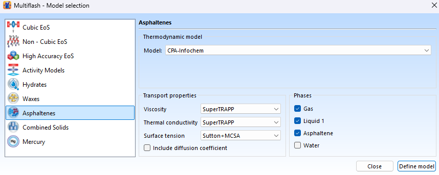
Figure2. Asphaltene Model Selection – 2
At this point, the default settings for the fluid state equation and asphaltene model will be displayed.Multiflash software recommends using three fluid models (CPA,RKSA,PR78A) in combination with the asphaltene model starting from version 7.2. It is important to note that the settings in the example file may differ from the default values.
Note: The default parameters for some asphaltene models are based on the RKSA fluid model development. If you use these default model parameters in asphaltene calculations, it is recommended to select the RKSA fluid model.
4.Modify the relevant options as needed.
Please select the appropriate transfer property parameter model to accurately describe the fluid phase; note that these models do not consider the effects of asphaltenes.
5.Click Define Model to complete the model definition.
6.After a success message appears, click OK.
7.In the “Fluid PVT” toolbar, clickPVT Analysis (PVT analysis), then enter your fluid components, contents, and properties (you can refer to the Multiflash software documentation “Defining a fluid using a PVT analysis” to input the relevant parameters), and ensure to input the values shown in the table below. Note that if you need to include water components in the fluid, be sure to add them only after completing the model calibration.
|
Item |
Value |
|
Pseudo components Normal fractions – Distribution start |
C6 |
|
Pseudo components Normal fractions – Pseudo components required |
15 |
|
Molecular weight |
If available, enter your experimental value. |
|
Specific gravity |
If available, enter your experimental value. |
|
SARA Analysis |
If available, enter your experimental value. If you do not have analysis data, or only have partial analysis that does not include resin/asphaltene ratios, please checkEstimate RA |
8.ClickDo characterization to perform fluid characterization, then click OK in the pop-up message box.
If fluid characterization is successfully completed, the fluid composition will change, including asphaltene components and resin components prefixed with “R” (e.g., R36-48).
9.According to the relevant instructions in “Asphaltene Fluid Modeling and Simulation in Multiflash (for details, refer to the upcoming third part: Model Calibration),” calibrate your model.
10.If you need to consider water components, please add them and their contents after completing the model calibration.
11.At this point, your model is ready for asphaltene calculations.
— END —
Author: Chen JiyunEditor: Yu Ting