Background of OPC Protocol
Before the emergence of OPC, the industrial automation field faced a significant challenge:
- Diverse hardware devices: Factories have PLCs, DCS, instruments, sensors, drives, etc., from hundreds of different manufacturers.
- Diverse software requirements: There are monitoring software (SCADA/HMI), Manufacturing Execution Systems (MES), historical databases, ERP systems, etc., from different companies.
- Diverse communication protocols: Each hardware manufacturer uses its proprietary communication protocols (such as Siemens S7, Rockwell DF1, Omron Host Link, Modicon Modbus, etc.).
This leads to an “N x M” integration dilemma. If I have N types of monitoring software that need to access M types of devices, then theoretically, N x M dedicated drivers need to be developed.
To end this chaotic situation, a group of major automation suppliers (including Siemens, Rockwell, Omron, etc.) jointly established a task force in 1996, ultimately formulating the OPC standard. OPC originally stood for OLE for Process Control, and has now been renamed Open Platform Communications. Its core idea is very clever: “standardized interfaces, not protocols.”
The birth of OPC is closely related to Microsoft’s Component Object Model (COM) and Distributed Component Object Model (DCOM) technologies.
OPC servers include protocol converters that can communicate with devices (such as PLCs) using their proprietary protocols (like Modbus, EtherNet/IP, S7, etc.). OPC servers continuously query predefined specific memory values in the devices, known as tags or points, and store them in a special database. Subsequently, OPC clients (such as Human-Machine Interfaces HMI) can communicate with the server using the common OPC protocol to retrieve the values of these tags/points.
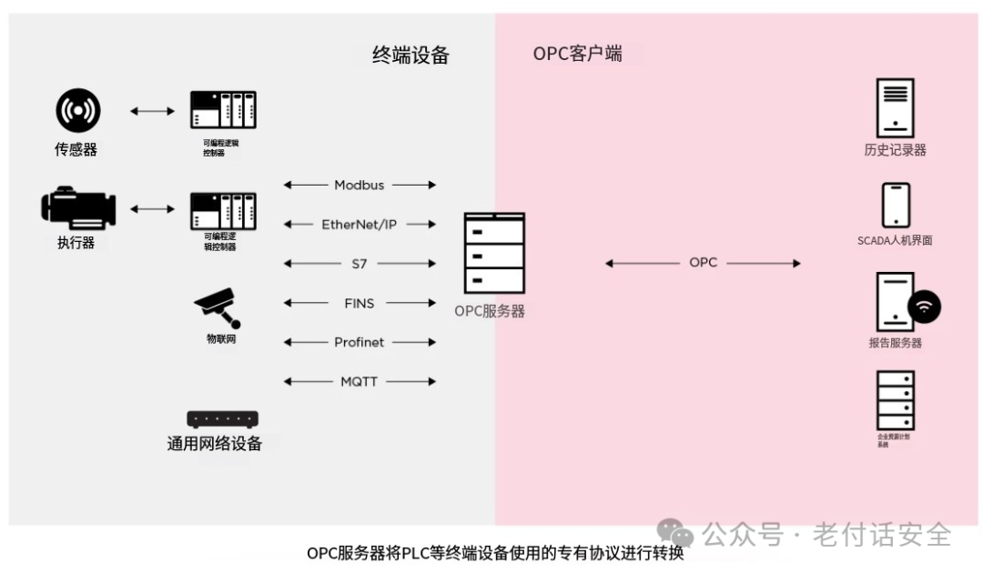
Due to the existence of numerous sub-protocols and transport layers, a new component must be introduced into the network architecture: the OPC gateway, also known as the OPC tunneler. The OPC gateway allows connections to be established between different OPC servers and OPC clients, regardless of the specific OPC protocol, vendor, version, or the number of connections supported by each OPC server. For example, using an OPC gateway, you can connect any OPC DA server or client to any OPC UA server or client, whether locally or through the factory network.
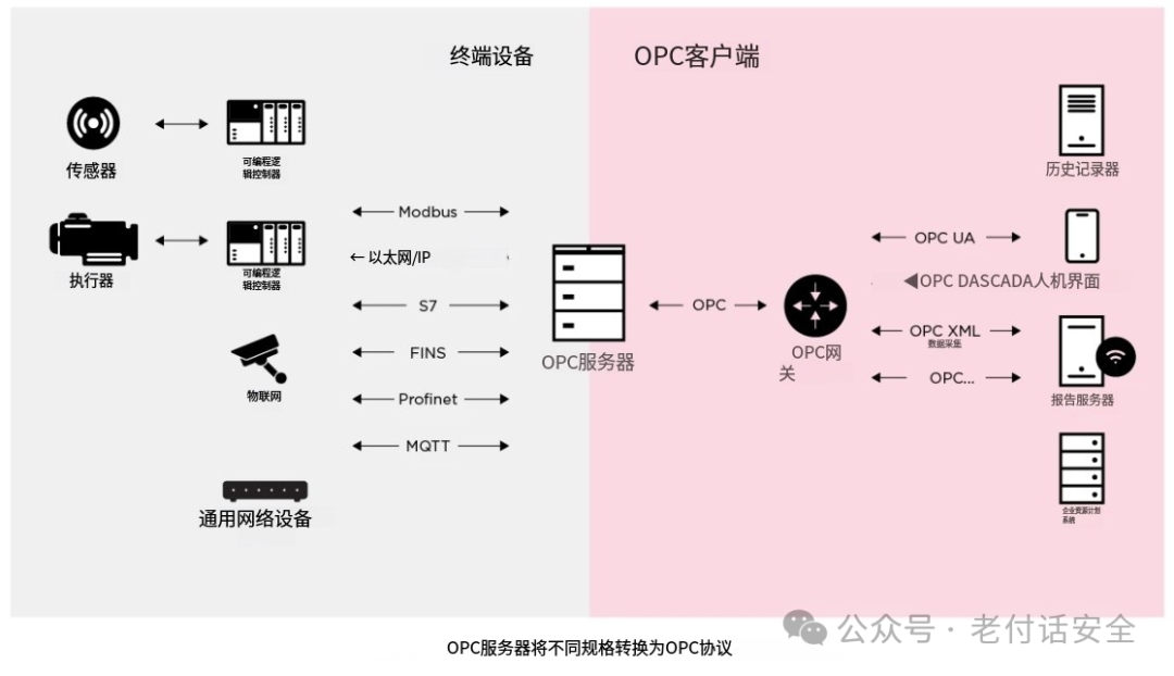
The OPC gateway primarily solves the conversion from Classic OPC (such as OPC DA) to Modern OPC UA. This allows older SCADA/HMI systems that only support OPC DA to communicate with next-generation MES/ERP systems that only support OPC UA. It breaks the traditional limitation of the number of client connections to OPC DA servers. The gateway connects as a client to the OPC DA server and then acts as a server, allowing multiple OPC UA clients to access this data simultaneously.
The architecture of OPC is developed based on DCOM:
-
Hardware manufacturers provide a “unified” driver (OPC Server):
-
Each hardware manufacturer only needs to write one driver that complies with the OPC standard for their devices, which is called the OPC Server.
-
The OPC Server internally knows how to communicate with its hardware through proprietary protocols, but it exposes a standard, unified OPC interface externally.
Software vendors access the “unified” interface (OPC Client):
-
Any upper-layer software (such as SCADA, MES) only needs to develop one program that can access the standard OPC interface, which is called the OPC Client.
-
The OPC Client does not need to care about what the underlying hardware is; it only needs to read and write data through the standard OPC interface.
OPC is not a single protocol, but a set of specifications to accommodate different data access needs.
-
OPC Classic (based on COM/DCOM)
Limitations of Classic OPC:
-
Platform dependency: Tightly bound to the Microsoft Windows platform.
-
Firewall unfriendly: DCOM configuration is complex, and it is very difficult and insecure to cross network firewalls.
-
Reliability issues: DCOM itself is not stable enough in industrial network environments.
-
OPC DA – Classic OPC Data Access; core function: real-time data access. It focuses on reading and writing current real-time data from data sources (such as PLCs, DCS, sensors). Data model: based on a “flat” address space. Data items are identified by a simple string (e.g., “Channel1.Device1.Tag1”). It has no built-in semantic description, and engineers need to rely on documentation or experience to know what this tag specifically represents (e.g., whether it is temperature, pressure, or motor status).
OPC UA – Unified ArchitectureTo overcome the limitations of Classic OPC, the OPC Foundation released OPC UA around 2006.
-
Platform independence: No longer reliant on COM/DCOM, can be implemented in C/C++, Java, .NET, etc., on any operating system (Windows, Linux, macOS, embedded systems).
-
Unified information model: Not only transmits data but also defines rich data types and object models that can describe complex relationships and semantic information between devices (e.g., “this motor drives that pump”).
-
Built-in security: Provides end-to-end security mechanisms, including encryption, signing, and authentication.
-
Scalability: From embedded sensors to cloud servers, OPC UA can be used.
-
Multiple communication methods: Supports TCP-based binary efficient communication and HTTP/WebSocket-based web services, making it easy to traverse firewalls.
OPC UA not only includes the real-time data functions of OPC DA but also natively integrates historical data, alarms and events, method calls, etc., making it a truly unified framework.
OPC Unified Architecture (OPC UA) encompasses various aspects of the OPC Real-Time Data Access Specification (OPC DA), OPC Historical Data Access Specification (OPC HDA), OPC Alarms/Events Access Specification (OPC A&E), and OPC Security Protocol, but has extended functionality on this basis.• The OPC Real-Time Data Access Specification (OPC DA) defines standards related to data values, update times, and data quality information.• The OPC Historical Data Access Specification (OPC HDA) defines methods for querying and analyzing historical data and data with timestamps.• The OPC Alarms and Events Access Specification (OPC AE) defines standards related to alarm and time-type message information, as well as state change management.
The fundamental difference between OPC UA and OPC DA:
Data is no longer just a value with quality; it can be organized into objects with types, attributes, methods, and inheritance relationships.
For example, a “motor” object can contain attributes such as “speed” (real-time data), “total running time” (historical data), and “overheat alarm” (event), and can define methods such as “start” and “stop.” This self-descriptive nature allows the system to understand the meaning of the data without external documentation.
OPC DA solves the question of “What is the data?” – it tells you the current value, timestamp, and quality of a data point.OPC UA solves the question of “What does the data mean?” – it tells you through the information model which device this data point comes from, what physical quantity it represents, what relationships it has with other data, and what operations can be performed.Here we focus on understanding the two protocols, OPC DA and OPC UA.
Analysis of OPC DA Protocol
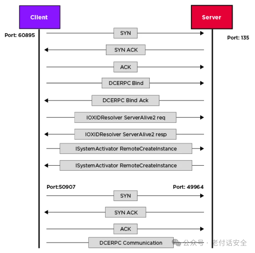
OPC DA is based on the DCOM architecture, with DCOM used as the underlying transport for OPC DA services. This means that the initial connection is built on top of the DCERPC connection – DCERPC is the remote procedure call used in distributed computing environments, equipped with OPC functionality. From a high-level perspective, the connection begins with the client initiating a DCOM connection, and then both parties synchronize the mapped interfaces, meaning each interface receives a unique identifier, allowing the client to use the functions exposed by the OPC interface, such as adding groups or items.
The connection process between OPC DA clients and servers:
-
Initial TCP connection (
<span>Port: 60895</span>)
-
SYN, SYN ACK, ACK: This is the standard TCP three-way handshake.
-
The client initiates a connection SYN from a random high port (60895) to the server’s known DCOM port (usually 135).
-
The server agrees to establish the connection SYN ACK.
-
The client confirms ACK, completing the TCP three-way handshake. The control channel is established.
-
DCERPC Bind, DCERPC Bind Ack: After this TCP connection is established, the client immediately initiates a DCE/RPC binding request on this connection.Specifying the UUID of the interface to be called (e.g., IOXIDResolver).
-
The server agrees to bind DCERPC Bind Ack, preparing to receive RPC requests.
-
The client queries the server IOXIDResolver ServerAlive2 req, asking for the IP and dynamic port it wishes to use for actual data transmission.
-
The server replies IOXIDResolver ServerAlive2 resp with its IP and a newly assigned dynamic port (shown as 50907, this port is random), for the client to establish a second data connection.
-
This process is to establish the RPC connection context, negotiate how to serialize data, etc. The server’s confirmation (Bind Ack) means both parties agree to perform RPC communication on this connection.
Endpoint resolution and dynamic port allocation
-
Based on the information obtained in the previous step, the client uses SYN from another random port (Port: 1395) to initiate a second TCP connection request to the server’s 50907 port.
-
The server agrees to establish the data connection SYN ACK.
-
The client confirms ACK, completing the second TCP three-way handshake. The data channel is established.
-
RPC communication begins on this data channel. DCERPC Communication
-
The client requests the server to create and activate an OPC Server object instance within the process corresponding to port 50907 through an RPC call (ISystemActivator RemoteCreateInstance). This is a key step in initiating OPC data exchange.ISystemActivator RemoteCreateInstance may be a retransmission or another related activation request. At this point, the OPC DA connection is ready, and subsequent actual OPC data read and write (Read, Write, Subscribe, etc.) will occur on this data channel.
-
IOXIDResolver ServerAlive2: This is the most critical step in the DCOM connection. The client queries the server through the initial connection (port 135), asking, “I want to communicate with a certain DCOM object (i.e., OPC Server), which port should you be listening on?”
Object activation and remote invocation
-
<span>ISystemActivator RemoteCreateInstance</span>: On the new connection (port 50907), the client sends a DCOM request to the server, requesting to “activate” the specified OPC Server object. This<span>RemoteCreateInstance</span>call is essentially a command for the server to start the OPC Server component process (e.g.,<span>OPCServer.WinCC</span>), and return an interface pointer that can communicate with it. After this, all OPC data read and write operations will occur on this connection.
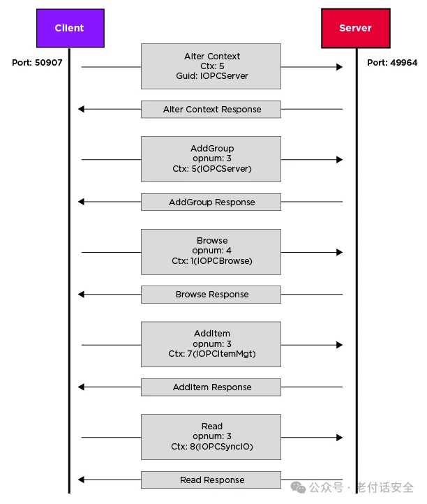
The typical OPC DA data packet flow for reading items from the OPC server:
-
The client (port 50907) sends an Alter Context request. The context (Ctx) is set to 5. Guld is specified as the IOPCServer interface. This is the standard operation for DCOM to switch or establish interface contexts.
- The server (port 49964) confirms (Alter Context Response) that the context switch was successful.
-
AddGroup (opnum: 3): The client calls the AddGroup method of the IOPCServer interface (operation number 3). Executed in context 5. The purpose is to create a data group (Group) on the server to manage a set of data items (Items).
- AddGroup Response: The server returns the result of creating the group (such as group handle, update rate, etc.).
-
The client calls the Browse method of the IOPCBrowse interface (operation number 4). The context switches to 1, indicating that the IOPCBrowse interface is now in use. This is used to browse data items (such as variables, tags) on the server.
- Browse Response: The server returns the browsing results (such as the list of available data items).
- AddItem (opnum: 3): The client calls the AddItem method of the IOPCItemMgt interface (operation number 3). The context switches to 7, indicating that the IOPCItemMgt interface is now in use. The purpose is to add one or more data items to the previously created group.
- AddItem Response: The server returns the result of adding the item (such as item handle, status, etc.).
- Read (opnum: 3): The client calls the Read method of the IOPCSyncIO interface (operation number 3). The context switches to 8, indicating that the IOPCSyncIO interface is now in use. This is used to synchronously read the current value of data items.
- Read Response: The server returns the read data value and timestamp information.

End
