In industrial wastewater treatment and municipal sewage systems, the stable operation of sewage pumps directly determines the efficiency of wastewater treatment and environmental safety. Traditional manual control or relay control systems have issues such as response delays, frequent failures, and high energy consumption, making it difficult to meet the precise control requirements of modern wastewater treatment. Programmable Logic Controllers (PLCs), with their high reliability, strong anti-interference capabilities, and flexible programming, have become the core technical support for sewage pump control. This article details the application design and implementation process of PLCs in wastewater treatment, based on a dual-pump control system example from a sewage pool.
1. System Control Requirements and Core Objectives
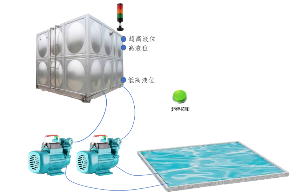
The control objects designed in this project are two sewage pumps paired with a single sewage pool, requiring fully automated control of sewage discharge. The specific requirements can be divided into four categories: start-stop logic, operation switching, liquid level self-adaptation, and abnormal alarm. The core objective is to ensure stable liquid levels in the sewage pool, avoid overflow or dry pump operation, and extend the equipment’s lifespan.
-
Safe Start-Stop Control: To prevent accidental touches from causing erroneous device startups, a long press of the start button for 3 seconds is designed to trigger device startup, with the running indicator light (Y1, green light) lighting up simultaneously; pressing the start button again will execute the stop operation, extinguishing the running indicator light, forming a convenient “one-button start-stop” operation mode.
-
Timed Cycle Operation: The two sewage pumps adopt a 5-minute timed pump switching mechanism to avoid uneven wear caused by long-term continuous operation of a single pump, balancing the workload of both devices and reducing maintenance costs.
-
Liquid Level Self-Adaptive Adjustment: The system dynamically adjusts the pump group operation status based on the sewage pool liquid level—automatically starting a single pump for drainage at high liquid levels; automatically shutting down the operating pump at low liquid levels to prevent dry running; when the liquid level reaches an ultra-high level, both pumps are triggered to run simultaneously to quickly lower the liquid level and prevent sewage overflow.
-
Abnormal Alarm Mechanism: A graded alarm function is set up, where at ultra-high liquid levels, the alarm light (Y0, yellow light) flashes at 0.5-second intervals, indicating an urgent drainage requirement; at ultra-low liquid levels, the alarm light remains on, warning operators to check the liquid level sensor or water supply situation.
2. System I/O Allocation and Hardware Architecture
The core of the PLC control system is to clarify the correspondence between input and output (I/O) signals and external devices. This system uses a small PLC configured with 4 input points and 4 output points, fully meeting control requirements. The specific I/O allocation is shown in the table below.
|
Input Point |
Corresponding Device |
Function Description |
Output Point |
Corresponding Device |
Function Description |
|---|---|---|---|---|---|
|
X0 |
Start Button |
Triggers device start-stop operation |
Y0 |
Liquid Level Alarm Light (Yellow Light) |
Indicates liquid level abnormal status |
|
X1 |
High Liquid Level Sensor |
Detects sewage reaching high liquid level |
Y1 |
Running Indicator Light (Green Light) |
Indicates device running status |
|
X2 |
Low Liquid Level Sensor |
Detects sewage dropping to low liquid level |
Y2 |
Sewage Pump 1 |
Core drainage execution device |
|
X3 |
Ultra-High Liquid Level Sensor |
Detects sewage reaching ultra-high level |
Y3 |
Sewage Pump 2 |
Core drainage execution device |
The system hardware architecture consists of the PLC main unit, liquid level sensors, start-stop buttons, sewage pumps, indicator lights, and alarm lights. The liquid level sensors collect sewage pool liquid level signals in real-time and transmit them to the PLC input terminals; the PLC sends control signals to the output terminals after internal program logic calculations, driving the sewage pumps’ start-stop and indicator light status switching, forming a closed-loop system of “signal collection – logic operation – execution control”.
3. Core Module Analysis of PLC Program Design
The PLC program adopts a modular design approach, divided into five major modules based on functionality: start-stop control, pump cycle control, ultra-high liquid level control, stop control, and alarm control. Each module forms a complete control system through logical associations. Special attention must be paid to the order of program writing, as PLCs follow the “top-down” scanning execution principle, and the arrangement order of modules directly affects control effectiveness.
3.1 Start-Stop Control Module: Safe Triggering and Status Switching
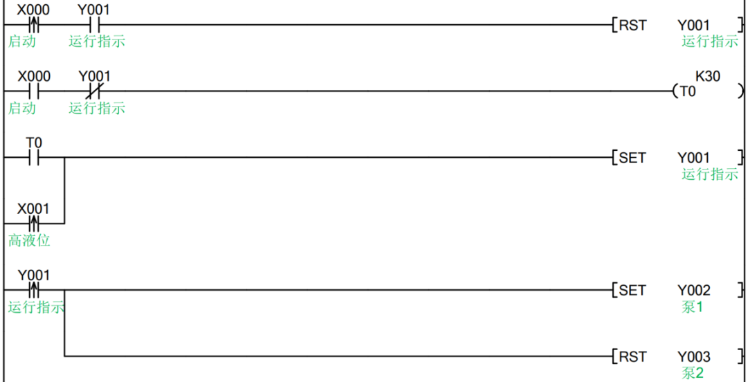
This module primarily addresses the issues of “accidental touch protection” and “status switching,” using timers to implement startup delays and achieving stop functionality through rising edge triggers. The program design is as follows:
-
Start Logic: The start button (X0) signal is connected to timer T0, with a set timing of 3 seconds (K30). When X0 remains closed for 3 seconds, timer T0 activates, its normally open contact closes, lighting up the running indicator light Y1 through a set instruction (SET), while sewage pump 1 (Y2) is set, and sewage pump 2 (Y3) remains in reset state, achieving device startup and initial pump group operation.
-
Stop Logic: While Y1 remains conductive (device running), pressing the start button X0 again triggers a reset instruction (RST) through its rising edge signal, resetting Y1, extinguishing the running indicator light, and stopping device operation.
-
Liquid Level Linked Start: When the high liquid level sensor X1 is triggered, the system automatically sets Y1, starting device operation without manual intervention, enhancing control automation.
3.2 Pump Cycle Control Module: Timed Pump Switching and Load Balancing
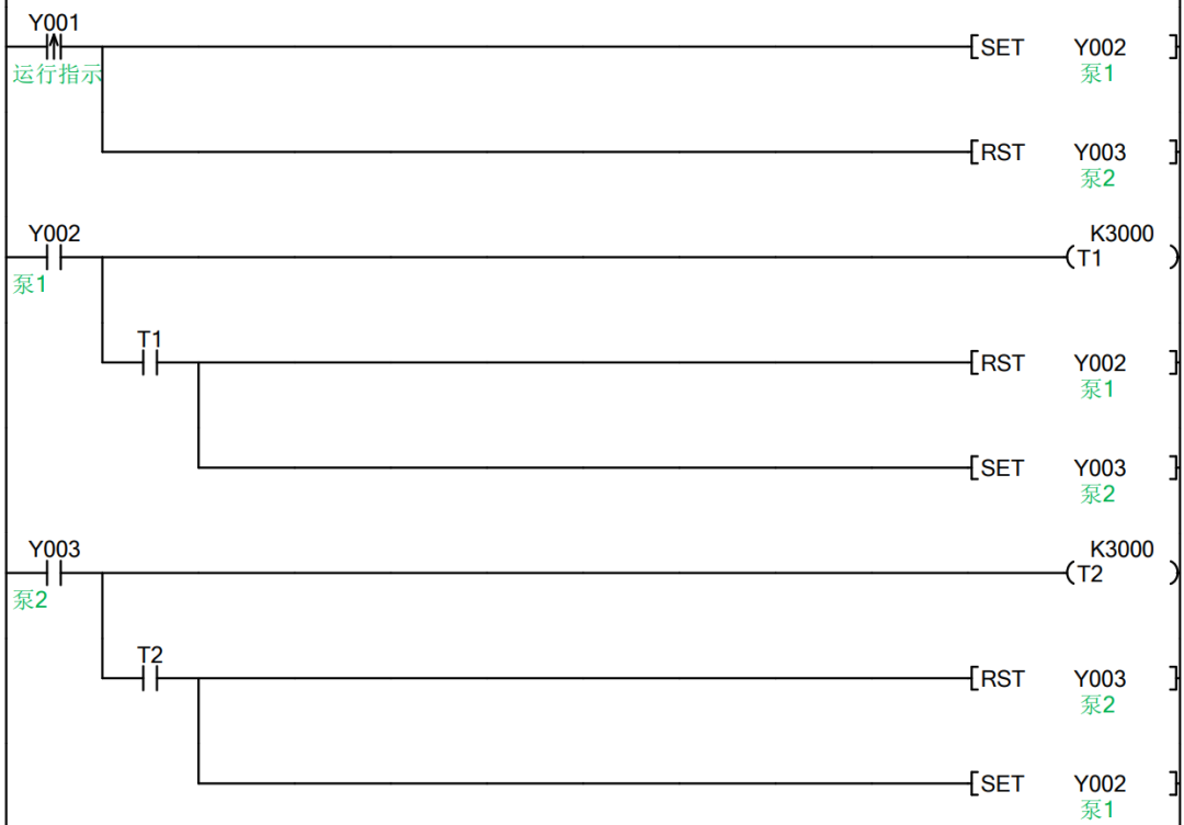
To achieve the requirement of switching between the two pumps every 5 minutes, two timers are designed to monitor the running time of each pump, using set/reset instructions to implement pump group switching. The program logic is shown in Figure 2-5-3:
-
Initial Start: When the rising edge of the high liquid level X1 signal is triggered, Y2 (starting pump 1) is set, while Y3 (stopping pump 2) is reset, ensuring single pump startup.
-
Pump 1 to Pump 2: When pump 1 (Y2) is running, its normally open contact closes, starting timer T1 (set to 5 minutes, i.e., K3000). When T1 times out, its normally open contact closes, triggering the reset of Y2 and setting Y3, achieving the switch from pump 1 stopping to pump 2 starting.
-
Pump 2 to Pump 1: When pump 2 (Y3) is running, its normally open contact closes, starting timer T2 (also set to K3000). After T2 times out, its normally open contact closes, triggering the reset of Y3 and setting Y2, completing the pump group cycle switching, and so on.
3.3 Ultra-High Liquid Level Control Module: Emergency Drainage and Priority Assurance
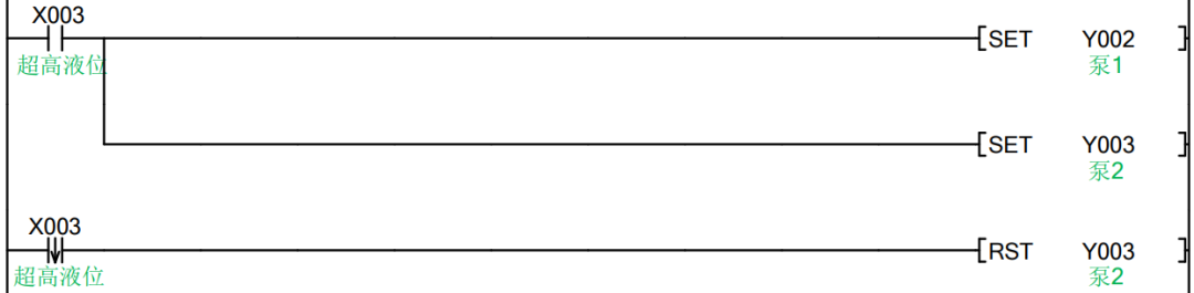
When the sewage liquid level reaches ultra-high level (triggered by X3), it is necessary to break through the conventional single pump operation mode and start both pumps for emergency drainage. This module’s program must be placed after the cycle control module to ensure the priority of ultra-high liquid level control:
-
Double Pump Start: When the X3 (ultra-high level) signal is conductive, both Y2 and Y3 are set simultaneously through set instructions, starting both sewage pumps to maximize drainage efficiency and quickly lower the liquid level.
-
Restore Single Pump Operation: When the liquid level drops and the X3 signal disconnects (falling edge trigger), the reset instruction resets Y3, leaving Y2 running, restoring the single pump cycle mode. It should be noted that the reset instruction triggered by the falling edge of X3 only acts on Y3 to avoid both pumps stopping simultaneously, which would interrupt drainage.
3.4 Stop Control Module: Safe Shutdown and Abnormal Protection
To ensure reliable shutdown of the device in a stopped state or at low liquid levels, a batch reset instruction is designed to achieve full stop of the pump group. This module must be placed after the ultra-high control module to avoid conflicts with the emergency drainage function, as shown in Figure 2-5-5:

When any of the following conditions are met, the batch reset instruction ZRST Y2 Y3 is triggered to stop both sewage pumps simultaneously: ① The running indicator light Y1 is off (device stopped), its normally closed contact closes; ② The low liquid level sensor X2 is triggered, its normally closed contact closes (indicating that the liquid level has dropped to low level, requiring the pump group to stop to avoid dry running). Through the batch reset instruction, the pump group is ensured to stop quickly and reliably, protecting equipment safety.
3.5 Alarm Control Module: Graded Prompting and Abnormal Warning
Graded alarms are implemented based on the type of liquid level anomaly, utilizing the PLC’s internal special relay M8013 (1-second cycle pulse signal) to achieve the flashing effect of the alarm light, as shown in Figure 2-5-6:

-
Ultra-High Level Flashing Alarm: When X3 (ultra-high level) is conductive, the normally open contact of M8013 controls Y0. Since M8013 conducts for 0.5 seconds and disconnects for 0.5 seconds, Y0 synchronously turns on and off, achieving the effect of the alarm light flashing at 0.5-second intervals, indicating an urgent anomaly.
-
Ultra-Low Liquid Level Steady Alarm: When the liquid level drops to ultra-low level, the low liquid level sensor X2 has no signal, its normally closed contact closes, and this signal is paralleled with the ultra-high level alarm signal to control Y0. At this time, Y0 remains conductive, and the alarm light stays on, prompting operators to check the cause of the liquid level anomaly.
4. System Application Effects and Technical Advantages
This PLC control system has shown significant advantages in practical applications: firstly, high automation level, achieving fully automated control of device start-stop and pump group switching through the linkage of liquid level sensors and PLC, reducing manual intervention and lowering operational costs; secondly, strong reliability, with the PLC’s anti-interference design ensuring stable operation in the humid and dusty environment of the wastewater treatment workshop, and the alarm mechanism promptly indicating anomalies to avoid equipment failures and sewage overflow risks; thirdly, energy consumption and maintenance optimization, with the timed pump switching mechanism balancing the load of both devices, extending the pump group’s lifespan and reducing maintenance frequency and costs.
Additionally, the system has good scalability; if subsequent wastewater treatment processes (such as dosing, filtration, etc.) need to be added, functionality upgrades can be achieved by expanding the PLC I/O modules and modifying the program to meet different control requirements in various scenarios.
5. Conclusion
The application of PLC technology in sewage pump control systems has realized the transition of wastewater treatment from “manual operation” to “intelligent control,” providing reliable technical support for the efficient and safe operation of the wastewater treatment industry. This article, through a specific case, elaborates on the modular design concept and core control logic of PLC programs, which can be promoted to various pump group control and liquid level control scenarios, providing references and insights for related industrial control projects. In the future, the integration of IoT technology with PLC applications can further achieve remote monitoring, fault diagnosis, and other functions, promoting the improvement of the intelligence level in wastewater treatment.
Since you’ve read this far, why not follow me ↓ The more people who like, share, and forward, the more motivated I will be to update!