Hello to all friends following Taiji Makers!
Welcome to the fifth article in the “AI Maker Project Development Communication” series. In the previous article, we completed the first phase of the “AI Green Plant Cultivation System”: the planning phase. During this phase, we described the project requirements to the AI, communicated to refine the details, and ultimately finalized the implementation plan and established the planning document. This groundwork laid a solid foundation for the subsequent code development.
Today, we will continue from the previous content and explain the subsequent work, namely: code generation, debugging, and project optimization.
If you haven’t read our previous article “Full Process of AI-Assisted Development for ESP32 Maker Projects (Part 1)”, I strongly recommend reading it before continuing.
Phase Two: Generation – Let AI Write Code While You Act as the “Commander”
The goal of this phase is clear: to have AI generate complete, compilable ESP32 Arduino code based on the implementation plan document we obtained in the first phase.
This operation consists of two steps:
The first step is to switch the collaboration mode of the Trae CN collaboration panel from Chat mode back to Builder mode.
The second step is to let the AI model use the “implementation plan” obtained from the first phase as a reference to generate complete, compilable ESP32 Arduino code based on that document.
Next, we will introduce these steps one by one:
Step 1 of Phase Two: Switch Collaboration Mode to Builder Mode
In the first phase of work introduced in the previous article, we switched the writing mode of Trae CN to Chat mode. We did this to allow the AI model to focus on communication. Now that we have reached the code generation phase, we need to switch the collaboration mode of Trae CN back to Builder mode—this is because the core function of Builder mode is to focus on code generation, which aligns better with our current goal of “generating project code”.
Step 2 of Phase Two: Generate Code Based on the “Implementation Plan”
After completing the mode switch, we can have the AI generate specific code based on the “project implementation plan document” established in the first phase.
At this point, you only need to enter clear instructions in the Trae CN dialog box, such as (the following blue italicized part):
—Code Generation Instruction Start—
Please generate complete ESP32 Arduino code based on the #Doc: project implementation plan document.md that we confirmed in our previous conversations, ensuring that the code structure is clear, includes necessary comments, and that hardware pin definitions and API call logic are consistent with the plan document.
For details related to API calls and response content parsing of the Silicon Flow AI platform that are not covered in the plan document, you may refer to the official online documentation of the Silicon Flow AI platform at:#Web:https://docs.siliconflow.cn/cn/api-reference/chat-completions/chat-completions
—Code Generation Instruction End—
After submitting the above instruction to the AI, it will generate the corresponding code based on the content of the implementation plan. However, I would like to share two practical tips with you.
Tip 1: Let Trae CN Directly “See” Our Reference File
Careful friends may have noticed that in the above blue prompt, we explicitly requested the AI to use “project implementation plan document.md” as a development reference. But have you ever thought about how the AI accurately finds this file?
Some may ask, “Isn’t the file name already written? Can’t the AI just find it by name?”
In fact, relying solely on manually entering the file name is not the most reliable method. On one hand, we may make typos, omissions, or even slight differences in case or punctuation when entering; on the other hand, AI cannot “understand” your intentions like humans. If there is any discrepancy in the file name, the AI may mistakenly use another similarly named document or even fail to find the target file, leading to output results deviating from expectations.
Currently, our project is still in the early stages, with few files and a simple structure, making it easy for the AI to locate the correct reference file. However, as the project progresses, with an increasing number of files and a more complex directory structure, relying solely on the file name will make it difficult to ensure that the AI accurately identifies the file we truly want to reference.
But you need not worry! We can directly “point to” the file for the AI, just like a teacher pointing to something on the blackboard in class—making it clear which file we are referring to.
The method is very simple:
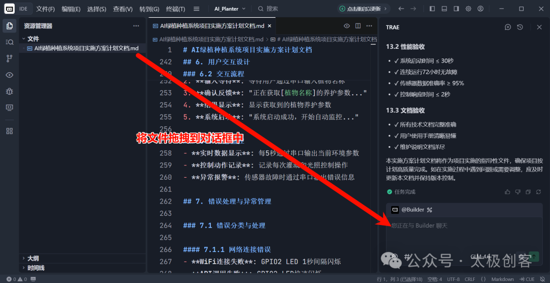
Just drag the target file directly into the prompt input box in the Trae CN project file browser (as indicated in the image below). At this point, the file name will automatically change color—indicating that the file has been successfully referenced. This way, the AI can clearly “see” and accurately use the reference content you specified, avoiding any ambiguity.
Tip 2: “Remind” AI to Use Online Resources
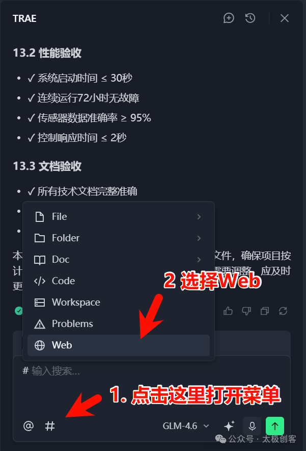
During project development, we sometimes need the AI to refer to some online resources, such as the “official documentation of the Silicon Flow AI platform” mentioned in the previous prompt. Typically, such external resources are not automatically included in the AI-generated plan document. To ensure that the AI clearly knows where to obtain these reference materials, we can use the “context menu” (as shown in the image below ↓).
1. Open Context Menu Example↓
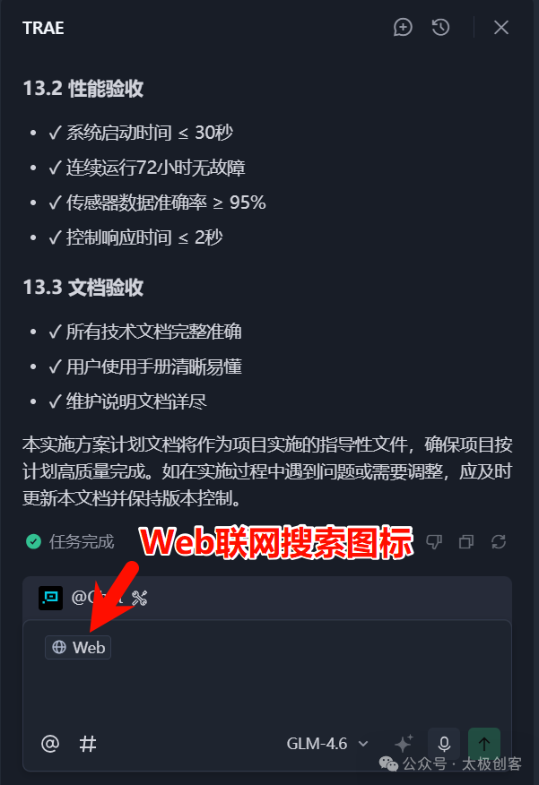
2. Click to select Web, and its icon will appear in the dialog box ↓
3. Add the online reference document URL to the Web search icon ↓
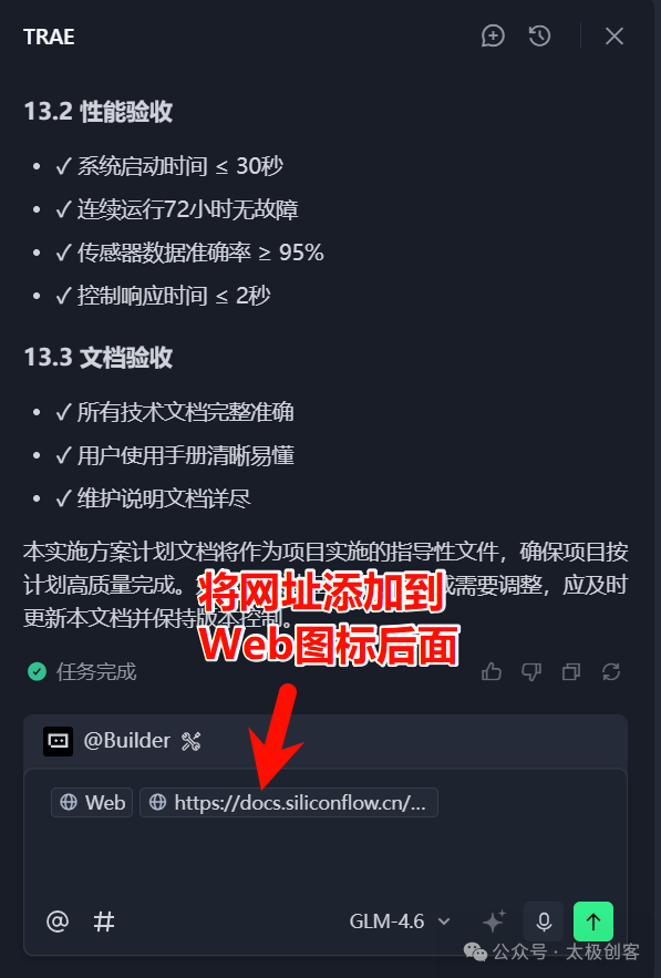
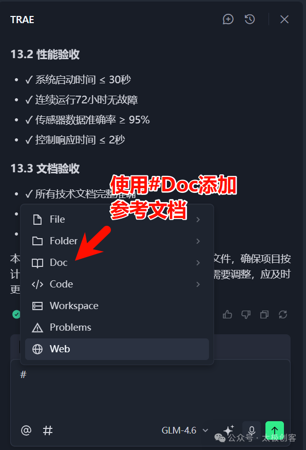
In fact, the function of this “context menu” goes far beyond this. It not only supports adding online links but also allows uploading local documents. For example, if you are developing a project that requires a specific communication protocol, and the detailed description exists only in a local document, you can submit this private document directly to the AI through the “Doc” option in the menu. This way, when the AI generates code or provides suggestions, it can use it as a key reference, significantly improving the accuracy and practicality of the output. (as shown in the image below ↓).
Now that we have covered these two tips, we can proceed to submit the instruction for the AI to generate project code based on our plan document.
After the AI generates the code, you can copy the code and paste it into the Arduino IDE for compilation:
-
If the compilation is successful, you can directly connect the ESP32 development board, click the “Upload” button, and test the actual running effect;
-
If the compilation fails (e.g., syntax error prompts), or if the functionality does not meet expectations after uploading (e.g., no data from the sensor, device not responding), there is no need to panic; we will address these issues in the upcoming “debugging phase”.
Phase Three: Debugging – Finding Bugs and Solving Problems with AI
During development, we often encounter situations that require debugging. Therefore, it is normal to need to debug code generated by AI. However, unlike debugging programs ourselves, the core of having AI assist in debugging is “precise feedback on issues”. This means providing the AI with a comprehensive understanding of the specific content and details of the problem so that it can take targeted action. Here, I will introduce several types of issues we may encounter during debugging and how to handle each situation.
Situation 1: Program Compilation Errors
-
Copy the complete “error message” from the bottom of the Arduino IDE and paste it into the Trae CN dialog box, while using the “context” menu to specify the name of the file that caused the error, informing the AI, “This piece of code encountered the following error during compilation; please help me fix it”;
-
After the AI fixes it, be sure to check what it modified and why it made those changes—such as whether it was a missing library reference, incorrect pin definition, or a syntax issue. This is actually a great learning opportunity that can help deepen your understanding of the Arduino language.
Situation 2: Encountering Functional Anomalies (e.g., inaccurate sensor readings, water pump not working):
-
Describe the phenomenon in detail, such as “The soil moisture sensor always shows 100%” or “After entering the plant name, the ESP32 did not call the API”;
-
Supplement troubleshooting information, such as “I checked the wiring; the VCC of the YL-69 is connected to 3.3V, and S is connected to GPIO34,” to help the AI locate the problem faster.
During the debugging process, please note that the AI is merely an “auxiliary tool” and not a “universal fixer”. Your cooperation is essential for efficiently resolving issues during debugging.
Phase Four: Optimization – Making the Project More Stable and Usable
The core of the optimization phase is to make the project code more stable and user-friendly. We can have the AI help refine the code and also combine our own usage experience to suggest improvements.
Here are some common optimization directions we have summarized, along with how to instruct the AI to implement work towards these optimization directions:
-
Optimize Device Operation: Propose optimization needs based on issues encountered during actual use, such as “The sensor readings fluctuate too much; can we make the data more stable?” or “The water pump starts too frequently; can we set an ‘interval time’ to avoid repeatedly turning the pump on and off in a short time, causing damage to the device?”. The AI will provide specific code modification plans based on your needs.
-
Enhance Device Stability: Have the AI modify the code to make the ESP32’s operation more stable. For example, add “filtering processing” to sensor data to avoid anomalies caused by excessive data fluctuations. Or add a “timeout retry mechanism” to the ESP32’s API requests (to avoid failures due to network fluctuations);
-
Code Simplification: The ESP32 has limited memory, so have the AI delete redundant code and simplify logic to make the code more efficient and high-quality;
-
Add Friendly Prompts: Output more status information in the serial monitor, such as “WiFi connection successful”, “Fetching plant care parameters”, “Water pump starting”, to help users understand the system’s operating status;
-
Improve Comments: Have the AI add comments to key code segments, such as “initialize sensor”, “parse API response data”, “control water pump switch”, to facilitate future maintenance.
This concludes the introduction to AI-assisted development for the ESP32 maker project. Next, to help everyone use AI-assisted tools more smoothly, we would like to supplement a few key knowledge points. These points are technical concepts and tools that may seem unfamiliar to new friends in the above process, and we hope the following introduction can provide some assistance to those just starting with AI maker development.
About AI Platforms That Can Be Called by ESP32
In the implementation plan of this project, we clearly specified the use of the “Silicon Flow” platform’s API to achieve interaction between the ESP32 and large language models. Some friends may ask: Why do we need such an AI platform? What role does it play in the entire system?
In simple terms, the AI platform acts as a “bridge”. Human users can easily converse with AI through graphical interfaces like web pages and apps, but embedded devices like the ESP32 do not have screens and cannot “click buttons”; they can only send structured requests through standard network protocols (such as HTTP). Therefore, to allow the ESP32 to “ask” the AI questions (e.g., “What is the suitable soil moisture for pothos?”), a service is needed that can receive machine requests, call the AI model, and return structured answers—this is the core function provided by the AI platform.
Currently, mainstream AI platforms in China can be roughly divided into two categories:
-
Dedicated Model Platforms: Built by large model vendors, providing only their own model services, such as DeepSeek, Kimi, etc., similar to “model brand specialty stores”;
-
Comprehensive Aggregation Platforms: Integrating multiple vendors’ large models, allowing users to switch models freely (such as Qwen, GLM, MiniMax, etc.), without needing to register or configure repeatedly, similar to an “AI model store”.
“Silicon Flow” belongs to the latter. We chose it as an example mainly based on the following considerations:
-
New users receive a free quota of 2 million tokens upon registration, sufficient to complete the entire project development and debugging;
-
The platform supports various mainstream open-source models, making it easy for beginners to compare the response effects of different models;
-
Provides clear API documentation and standardized request/response formats, reducing the difficulty of integrating embedded devices.
It should be noted that this article recommends this platform purely based on technical applicability and teaching convenience, and no commercial sponsorship has been received. Developers can completely choose other compatible AI platforms based on their needs, simply adjusting the API endpoints, authentication methods, and request body structures accordingly.
We will provide a more detailed introduction to the AI platform in subsequent articles. Additionally, our ongoing ESP32 artificial intelligence IoT tutorial will also include detailed explanations on how to use the ESP32 to call the AI platform. Stay tuned.
Now, after introducing the AI platform, let’s briefly discuss the collaboration modes of the AI platform. The different modes provided by Trae CN each have their focus, and understanding their applicable scenarios can allow you to seamlessly switch between “discussing ideas” and “producing code”, significantly improving development efficiency. Below, we will clearly compare the two core modes.
Mode Summary: Chat Mode vs. Builder Mode
-
Chat Mode: Suitable for “discussing requirements, refining plans, consulting questions”—for example, determining project details, asking the AI for development suggestions, or consulting reasons for bugs, all can be done in this mode. Its core is “dialogue interaction”;
-
Builder Mode: Suitable for “generating code, optimizing code, generating project documentation”—when the requirements are clear, let the AI write code or optimize code, all can be done in this mode. Its core is “producing results”.
As for the “Builder with MCP mode”, its functionality is more complex and suitable for multi-file, large project development; we will explain it in detail in subsequent articles, so we won’t elaborate here.

Conclusion
Looking back at the entire process of AI-assisted development for the ESP32 maker project, we can clearly see that true efficient development is not about having AI “do the work for you”, but rather about “co-creating” with AI. In this concluding section of the article, let’s briefly review the entire AI-assisted development process for the ESP32 maker project to help everyone quickly organize:
-
Planning Phase: First, provide a detailed project introduction (including hardware, network, API, etc.) to let the AI understand the core requirements, then switch to Chat mode to discuss additional details and resolve questions with the AI, ultimately confirming and generating the project implementation plan document to set the direction for code generation;
-
Generation Phase: Based on the confirmed implementation plan, have the AI generate complete Arduino code and copy it to the Arduino IDE for verification and compilation;
-
Debugging Phase: If the code compilation reports errors or functional anomalies, provide specific feedback to the AI, collaborate with the AI to locate and fix the issues, while actively learning the causes of the problems;
-
Optimization Phase: For stable running code, propose optimization needs such as simplification, enhancing stability, and improving prompts/comments, allowing the AI to refine the code and enhance the project’s practicality.
AI can indeed help you save a lot of repetitive labor, avoid common pitfalls, and even inspire new implementation ideas, but it cannot replace your grasp of project goals, judgment of details, and validation of results. Only when you clearly express your needs, actively participate in debugging, and continuously provide feedback for optimization can AI truly become your reliable development partner.
I hope this full process example of the “Artificial Intelligence Green Plant Cultivation Control System” not only helps you master the practical methods of combining Trae CN with ESP32 but also establishes a reusable AI-assisted development thinking framework. In the future, regardless of the maker project you face, you will be able to plan calmly and implement efficiently.
Thank you for accompanying us on this journey; we grow together!
#Trae #ESP32 #Arduino #AI #ArtificialIntelligence #AIProgramming #Maker #IoT #AI #ArtificialIntelligenceIoT