Click blue words to followServo and Motion Control

The following video is sourced from the Zheng Motion Assistant
Advanced Application of EtherCAT Bus Motion Controller
In the previous section, we covered a quick introduction to the EtherCAT bus, including initialization, enabling, characteristics and switching of control modes, and basic settings. This section mainly focuses on parameter settings for the EtherCAT bus.
1. Material Preparation
1. Hardware
A. One ZMC432 controller with EtherCAT bus interface.
B. A set of Panasonic EtherCAT servo driver and motor.
C. One computer.
D. Two shielded Ethernet cables.
E. One 24V DC power supply.
F. Several terminal blocks and connection wires.
2. Software
A. ZDevelop V3.10 version controller programming software.
Download the compressed package from Zheng Motion’s official website www.zmotion.com.cn, unzip it and run the application directly without installation.
B. Panasonic servo driver upper computer debugging software.
Download and install from the Panasonic official website.

2. Hardware Wiring
1. Controller Wiring
Refer to the diagram below for the purpose of the controller interface.
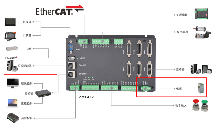
A. Main power supply: Connect the E+24V terminal on the controller’s main power terminal to the positive terminal of the 24V DC power supply, and connect the EGND terminal to the negative terminal of the 24V DC power supply.
B. Ethernet port wiring: Use an Ethernet cable to connect the controller’s Ethernet port to the computer’s Ethernet port.
C. Servo driver and controller wiring: Use an Ethernet cable to connect the controller’s EtherCAT bus port to the servo driver’s X2A or X2B port.
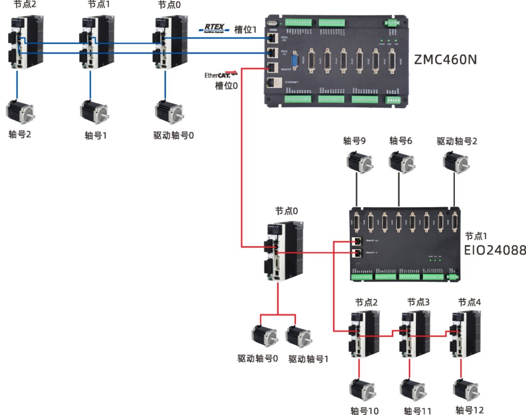
Note that the EtherCAT interface of the servo driver has two ports. Some drivers can connect these two ports freely, while others are divided into EtherCAT IN and EtherCAT OUT. The IN port connects to the previous device, and the OUT port connects to the next device. They cannot be mixed, so be careful with the connection order.
For multi-axis control, the EtherCAT OUT port of the servo driver is connected to the EtherCAT IN port of the next-level driving device, and so on.
2. Driver Wiring
Refer to the driver manual for the wiring of the servo driver with the motor and encoder, and connect the driver to the 220V mains.
The controller can be connected to the computer via serial port or Ethernet port. Below, we will elaborate on the Ethernet port connection method.
1. Ethernet Communication Operation Method
First, connect the controller and the computer with an Ethernet cable, turn on the power of the controller, then open the ZDevelop programming software, click on the menu bar “Controller” → “Connect” to open the “Connect to Controller” window.
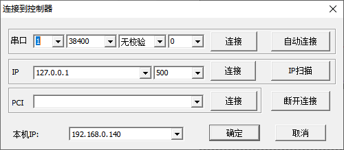
In the “Connect to Controller” window, you can quickly view the local IP and check whether the controller and the computer are in the same subnet.
When selecting from the IP address list, it will automatically search for available controller IP addresses in the current local area network (the controller’s POWER and RUN lights must be on to find the IP address).
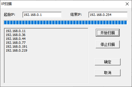
If there are multiple controllers on the same network, and the target controller’s IP address is not displayed in the drop-down list, you can use IP scanning to view all available controller IP addresses. After scanning, make sure to close this window and re-select from the IP drop-down list.
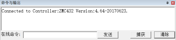
Select the correct IP address, click connect, and the programming software will successfully connect to the controller, displaying information in the online command and output window.
The default IP address of the controller is 192.168.0.11. The “Connect to Controller” window can display the local IP address. Please pay attention to set the wired and wireless network cards’ IP addresses separately. The computer needs to set its IP address to be in the same subnet as the controller’s IP address, meaning the first three segments must be the same, and the last segment must be different to communicate.
If the controller and the computer are not in the same subnet, one of their IP addresses needs to be modified to ensure both are in the same subnet.
To modify the controller’s IP address, you need to first connect to the controller using the serial port to obtain the controller’s IP address, then modify either the local machine’s IP or the controller’s IP to ensure they are in the same subnet.
2. Modifying the Controller’s IP Address
First, connect to the controller using the serial port to obtain the controller’s IP address, and then modify the controller’s IP address.
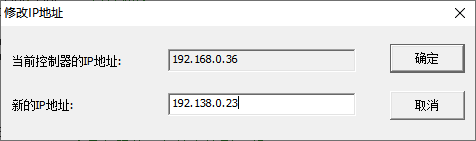
Method 1: You can directly modify the controller’s IP address through the menu bar “Controller” → “Modify IP Address” window.
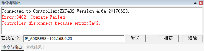
Method 2: Use the IP_ADDRESS command to send an online command for modification.
After the command is sent successfully, the connection will be automatically disconnected, and the online command will print the controller connection error message. Connect again using the new IP address 192.168.0.23, and the IP address modification will be permanently effective after success.
3. Modifying Local Machine’s IP Address
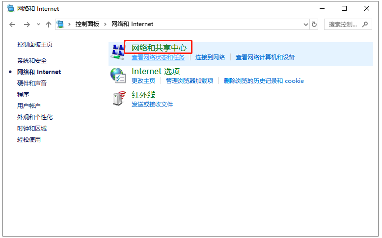
Taking WIN10 as an example, open the control panel from the start menu, and then open “Network and Internet”.

Then open “Network and Sharing Center”.
Click “Ethernet”.

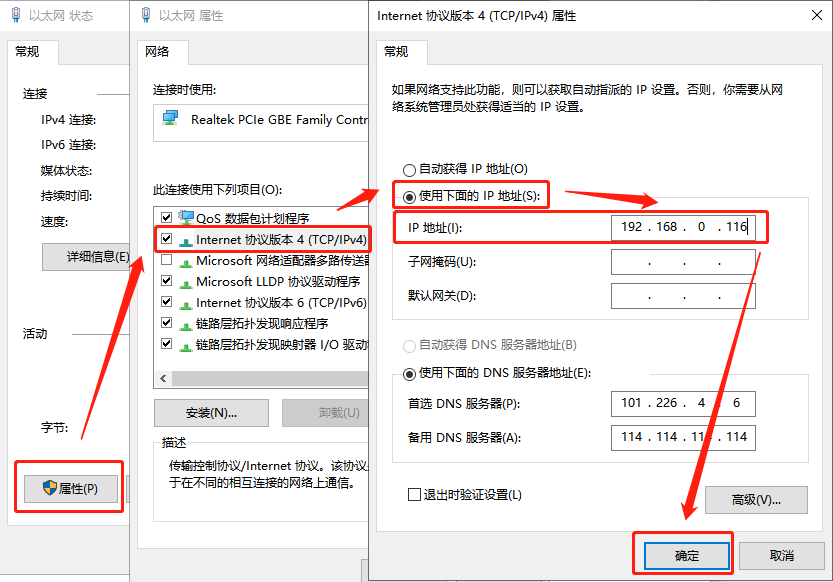
In the “Ethernet Status” window, click “Properties” to open the “Ethernet Properties” window. Find Internet Protocol Version 4 (TCP/IPv4) and open it to see the local IP address modification window. Check “Use the following IP address”, modify the IP in the IP address input box to be in the same subnet as the controller’s IP, and click “OK” to successfully modify the IP.
Try to connect to the controller again by reopening the “Connect to Controller” window.
DPOS is the user-defined target position, which is the command position sent by the controller, measured in UNITS. The value is equal to the actual pulse count sent by the controller divided by the pulse equivalent.
Writing DPOS will automatically convert to DEFPOS absolute coordinate position offset without moving the motor.
MPOS is the actual position measured by the user unit axis, also known as the actual position, measured in UNITS. This value is derived from the actual position measured by the encoder, which is attached to the servo motor to measure the motor’s rotation angle and speed. The value of MPOS will normally follow the value of DPOS, and it is equal to the actual pulse count measured by the encoder divided by the pulse equivalent. In cases without an encoder, the MPOS value of the axis automatically copies the value of DPOS.
Writing MPOS will automatically convert to DEFPOS absolute coordinate position offset.
Some motors have a certain following error (DPOS-MPOS), which relates to the rigidity of both the machinery and the motor. The better the machinery and the motor, and the more sufficient the rigidity adjustment, the smaller the following error. However, the following error will always exist, cannot be eliminated, and varies in real-time. In practical applications, efforts should be made to enhance the mechanical and motor rigidity to minimize the following error and achieve smoother speed, making MPOS more accurate.
Additionally, SPEED is the speed given by the controller, and MSPEED is the actual measured feedback speed from the encoder.
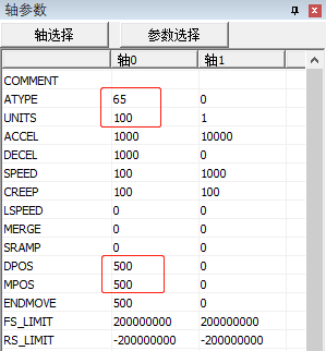
As shown in the figure below, axis type ATYPE=65, EtherCAT cyclic position mode, with encoder feedback, thus both pulse signal output and encoder feedback signal are on axis 0, at this time MPOS is true and follows DPOS.
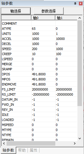
When ATYPE=4 or 65 or 50 mode, all axes have encoder feedback.
The OFFPOS command modifies all coordinates relatively and does not affect movements that have already been executed or are in the buffer.
The DEFPOS command sets the current axis position to a new absolute position value and does not affect movements that have already been executed or are in the buffer.
Example:
BASE(0,1) 'Select axis 0, axis 1DPOS=100,100 'Set current position to 100,100?DPOS(0),DPOS(1) 'Print confirmation, current position is 100,100OFFPOS=10,20 'Multiple calls to OFFPOS relative positionOFFPOS=10,20?DPOS(0),DPOS(1) 'At this moment, the current position becomes 120,140DEFPOS(10,20) 'Set current position to 10,20?DPOS(0),DPOS(1) 'Current position is 10,20
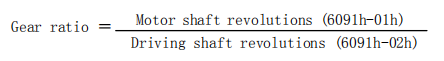
1. Application of Electronic Gear Ratio
The electronic gear ratio of the servo motor refers to amplifying or reducing the pulse frequency received by the controller. One parameter is the numerator, and the other is the denominator. If the ratio of the numerator to the denominator is greater than 1, it is amplified; if less than 1, it is reduced; and if equal to 1, the number of pulses received by the motor equals the number of pulses sent by the controller.
Calculation formula: Actual pulses received by the motor = Pulses sent by the controller * Electronic gear ratio
For example: If the controller sends 10,000 pulses, and the numerator of the electronic gear ratio is set to 1, and the denominator is set to 2, the electronic gear ratio is 0.5, then the servo actually runs according to 5,000 pulses. If the controller sends 10,000 pulses, and the numerator is set to 2, and the denominator is set to 1, the electronic gear ratio is 2, then the servo actually runs according to 20,000 pulses.
The electronic gear ratio of the Panasonic driver is effective in the range of 1000-1/1000.
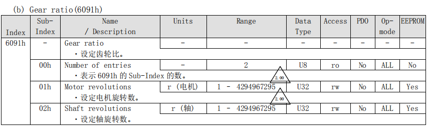
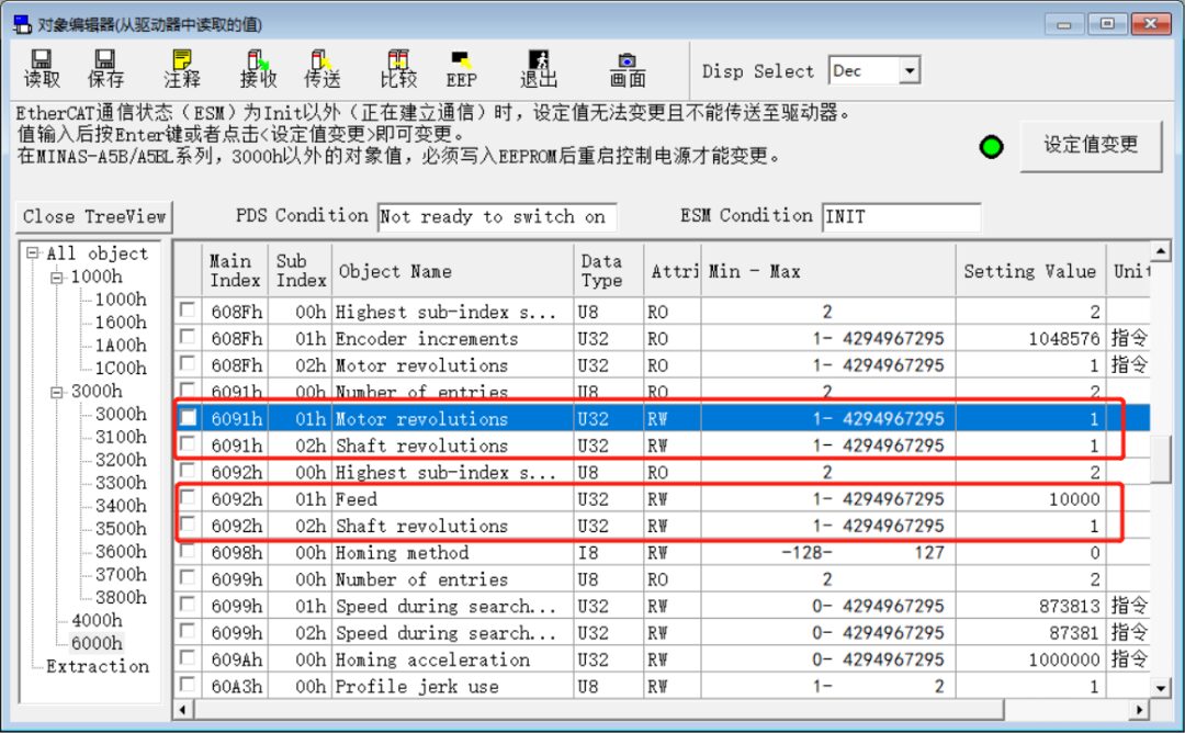
The electronic gear ratio is set through the sub-dictionary 01h and 02h of the data dictionary 6091h. 6091h-01h sets the numerator of the electronic gear ratio,6091h-02h sets the denominator of the electronic gear ratio.
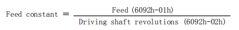
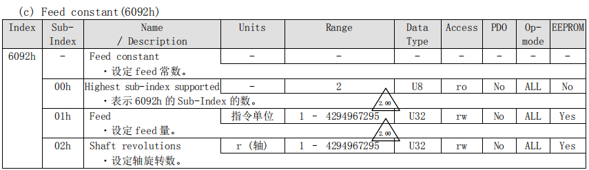
Sub-dictionary 01h of data dictionary 6092h is used to set the number of pulses required for the motor to rotate one circle, generally set according to the resolution of the encoder. The value of sub-dictionary 02h of 6092h defaults to 1.
Modifications to the electronic gear ratio and related parameters of the driver can be directly changed through the driver software or configured using SDO commands to read and write the corresponding data dictionary.
1. Modify Electronic Gear Ratio via Driver Software
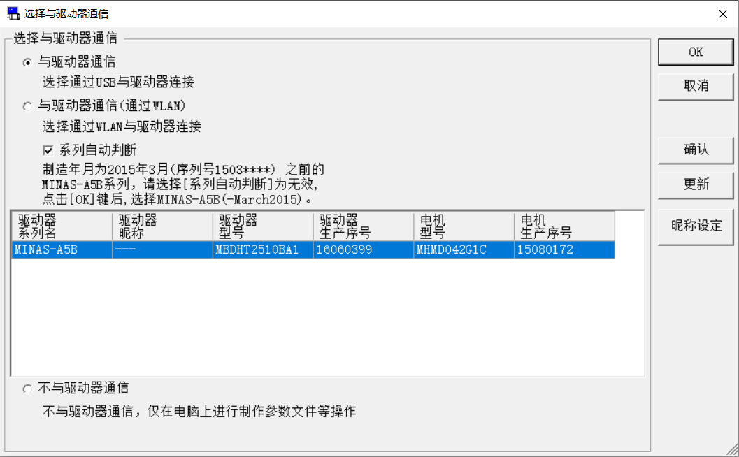
To modify the driver parameters, first connect to the driver, you can choose to connect the driver via USB or WLAN. Use a USB cable to connect the computer to the X1 port of the driver, power on the driver, open the Panasonic driver software PANATERM, and a window will pop up to select communication with the driver. After selecting the USB connection with the driver, the driver information will be automatically obtained and displayed in the window. Click OK to connect successfully and you can set the driver.
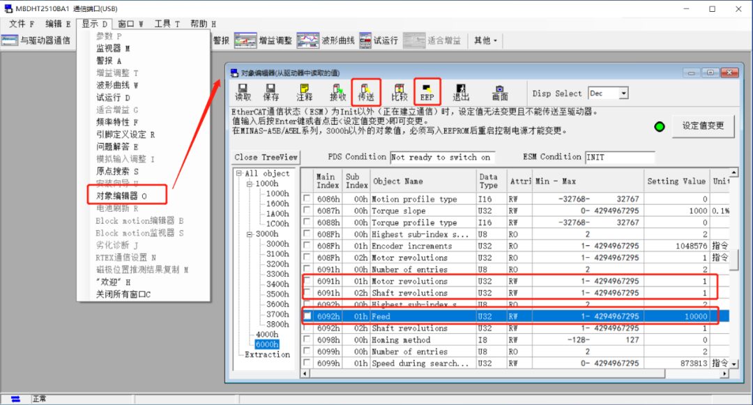
Click on the menu bar “Display” → “Object Editor” to open the window below, find the data dictionary that needs to be set, and directly modify the content of the data dictionary in the “Setting Value” column.
After modification, transfer the parameters to the driver and write them into the driver’s EEPROM. The parameters will take effect after the driver is powered on again.
In the figure, the electronic gear ratio = 1:1, and the number of pulses for the motor to rotate one circle is 10,000.
2. Modify Electronic Gear Ratio via SDO Command
SDO commands include reading from the data dictionary SDO_READ, SDO_READ_AXIS, and writing to the data dictionary SDO_WRITE, SDO_WRITE_AXIS.
Syntax for reading from the data dictionary:
SDO_READ (slot number, device ID, data dictionary number, sub-number, data type, location to store read data in TABLE)
SDO_READ_AXIS (axis number, data dictionary number, sub-number, data type, location to store read data in TABLE)
Syntax for writing to the data dictionary:
SDO_WRITE (slot number, device ID, data dictionary number, sub-number, data type, value to write)
SDO_WRITE_AXIS (axis number, data dictionary number, sub-number, data type, value to write)
Example:
SDO_WRITE(Bus_Slot,iNode,$6091,1,7,1) 'Set the numerator of the electronic gear ratio to 1SDO_WRITE(Bus_Slot,iNode,$6091,2,7,1) 'Set the denominator of the electronic gear ratio to 1SDO_WRITE(Bus_Slot,iNode,$6092,1,7,10000) 'Set the number of pulses for the motor to rotate one circle to 10000SDO_WRITE(Bus_Slot,iNode,$1010,1,7,$65766173)'Write to EEPROM (the driver needs to be powered on again after writing to EEPROM)After completing the command changes, check the driver parameters as follows:
2. Read Multi-turn Encoder Value
When the driver has a multi-turn absolute encoder, the ENCODE command can be used to read the raw value of the encoder hardware register, which is the multi-turn absolute value. This parameter is read-only type and can only be read when configured with an encoder in the ATYPE.
After the driver restarts, the ENCODE value will reset to zero.
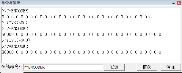
?*ENCODER 'Print each axis encoder value, the initial value of the driver is 0?ENCODER(0) 'Print single-axis encoder value?ENCODER AXIS(0) 'Print single-axis encoder valueAs shown in the figure below, using the EtherCAT driver with encoder feedback, controlling axis 0 to move continuously in the positive direction MOVE(500), the total number of pulses sent = UNITS * DPOS = 100 * 500 = 50000.
The ENCODE command reads the value of the multi-turn absolute encoder from the driver, equal to the total number of pulses received by the encoder, which is 50000.
At this moment, changing DPOS and MPOS will not change the value of ENCODE because the motor will not move when the coordinates are modified, and the number of pulses received by the encoder has not changed.
Since the value read is the multi-turn absolute value, the ENCODE value decreases when moving in the negative direction and increases when moving in the positive direction.
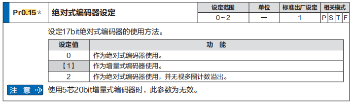
The Panasonic driver software can set the absolute encoder.
Set through parameter Pr0.15.
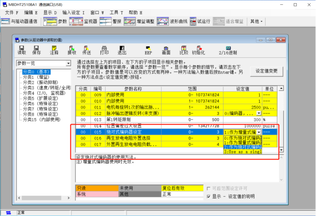
Explanation of parameter selection for Pr0.15: The three set values are explained below, the upper example is the default value 1, used as an incremental encoder.
3. Driver IO Operations
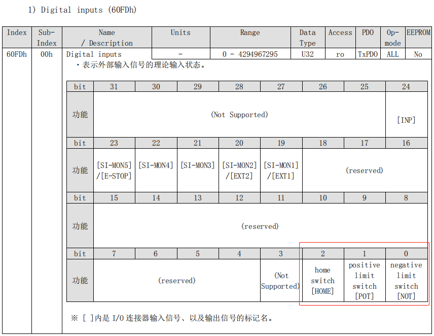
Before operating the driver’s inputs and outputs, map the driver IO input starting IO number of 60FDh and driver IO output of 60FEh in the driver’s object dictionary through the DRIVE_IO command.
After mapping the IO signals, control the driver’s IO signals based on the number. The IO signal output can be controlled using the OP command.
Setting the value of the bit to 1 means ON, while 0 means OFF.
Driver IO mapping example: Map positive and negative limit signals
Correctly setting the DRIVE_PROFILE or PDO is necessary for normal input mapping, meaning the DRIVE_PROFILE PDO configuration mode must include the data dictionary 60FDh and 60FEh.
DRIVE_PROFILE(iAxis) = 5 'Set corresponding PDO mode with IO mappingDRIVE_IO(iAxis) = i_IoNum 'Set starting IO numberREV_IN(iAxis) = i_IoNum 'Negative limit corresponds to 60FD BIT0FWD_IN(iAxis) = i_IoNum + 1 'Positive limit corresponds to 60FD BIT1DATUM_IN(i_IoNum) = i_IoNum + 2 'Origin signal corresponds to 60FD BIT2INVERT_IN(i_IoNum,ON) 'Special signal effective level inversionINVERT_IN(i_IoNum + 1,ON)INVERT_IN(i_IoNum + 2,ON)Driver IO output:
DRIVE_PROFILE(iAxis) = 5'Set corresponding PDO mode with IO mappingDRIVE_IO(iAxis) = i_IoNum'Set starting IO numberOP(i_IoNum,ON) 'Open the first OUT port of the driver
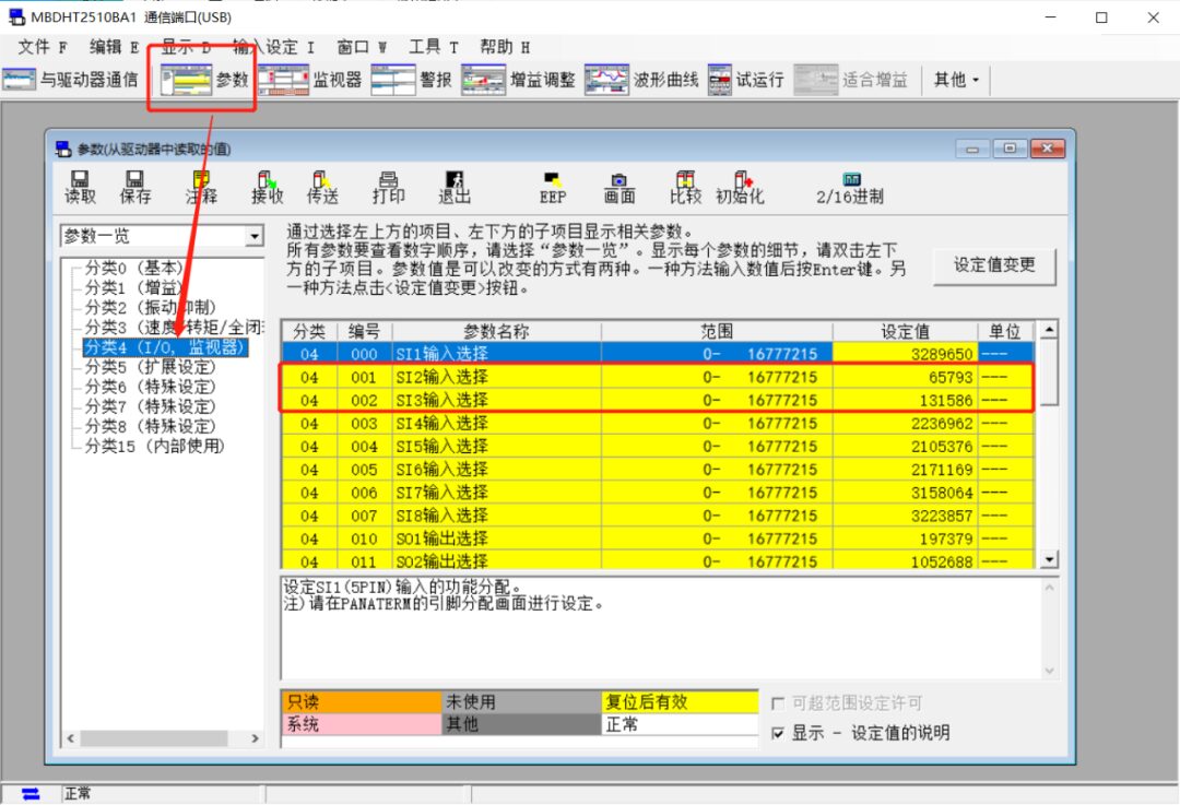
In the driver’s “Parameters” window, find parameter category 4 to operate the driver’s IO signals, as shown below.
4. Driver Homing
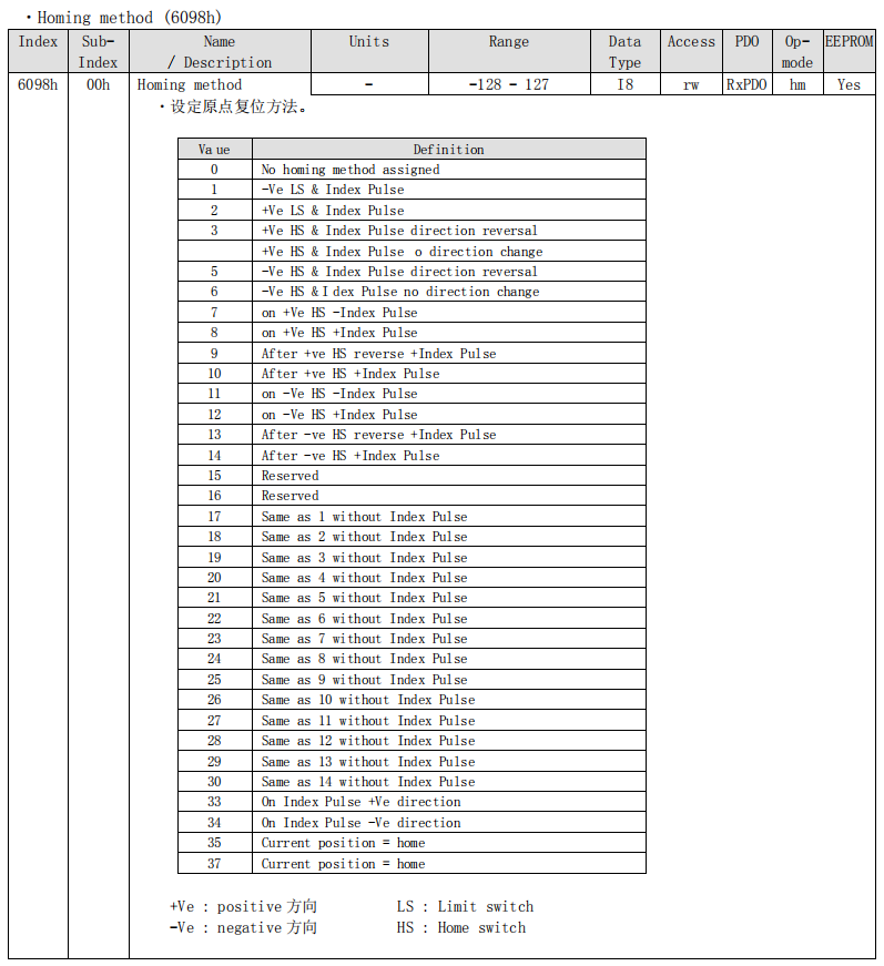
The EtherCAT bus can use the homing method provided by the controller DATUM(mode), with the mode value selection referring to the ZBasic programming manual’s DATUM command. The EtherCAT bus can also use the driver’s own homing mode.
The driver’s own homing uses the DATUM(21,mode2) command, where the mode2 value is to be checked in the driver manual data dictionary 6098h homing mode, as shown in the figure below. Fill in the corresponding Value value for mode2, the default value for mode2 is 0, which is also the driver’s homing mode. Note that the limit signals and origin signals must be connected to the driver, so to use the driver’s homing, the driver’s IO must be mapped.
Example:
After initialization is complete, run the driver’s homing program, as per the example in the previous section, map the driver’s limit signal and origin signal to the controller’s IO, and then run the following homing program.
BASE(iAxis) 'Homing for each driver axis numberAXIS_STOPREASON = 0SPEED = 100 'Homing speedCREEP = 10 'Reverse search speedACCEL = 1000DATUM(21,2) 'Driver homing mode value=2WAIT IDLEIF AXIS_STOPREASON = 0 THEN?