 What is EtherCAT
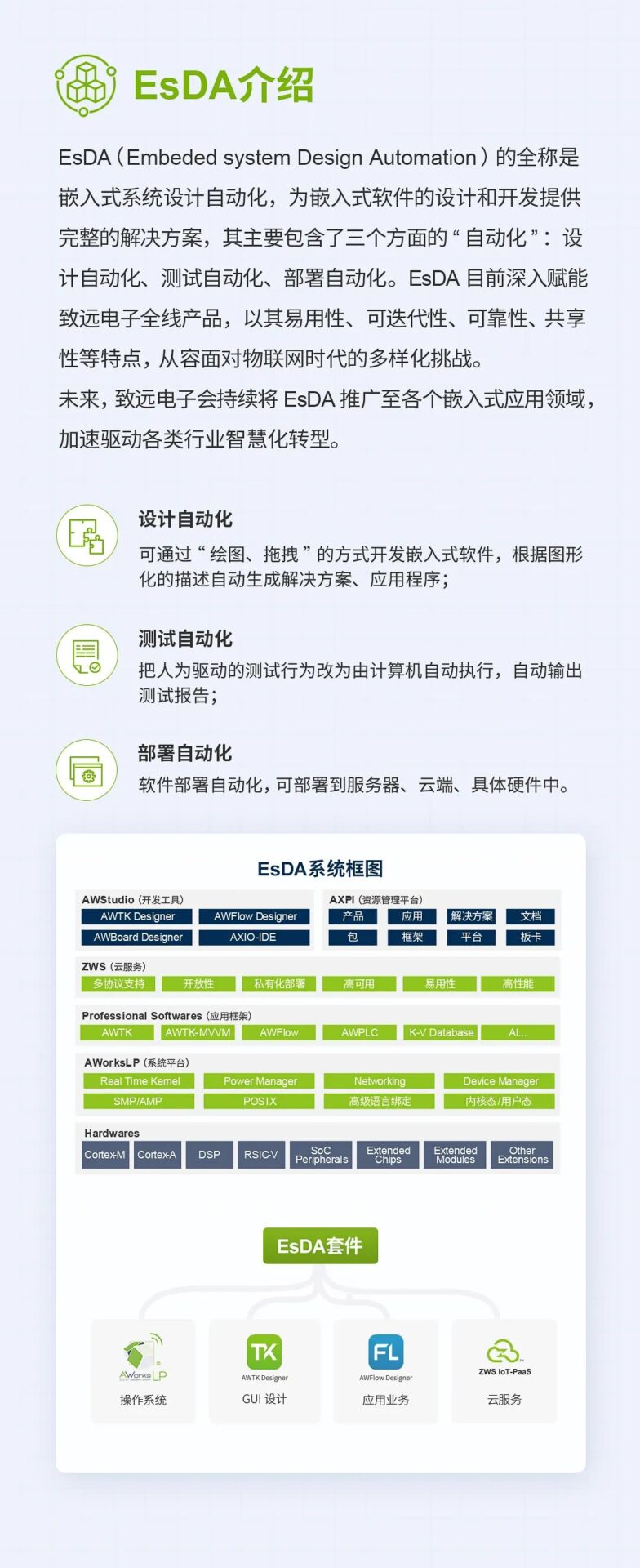
EtherCAT (Ethernet for Control Automation Technology) is an open architecture fieldbus system based on Ethernet, originally developed by Beckhoff in Germany. EtherCAT sets a new standard for the system’s real-time performance and topology flexibility, and it is an open protocol managed by the current EtherCAT Technology Group (ETG).
 Why Choose EtherCAT
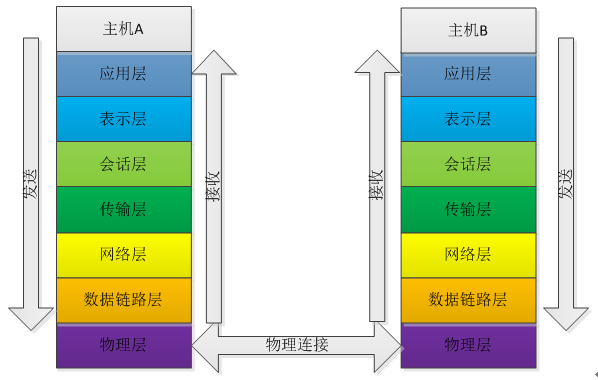
RS232 and RS485 belong to the physical layer of the ISO seven-layer structure. To achieve complete communication, the data link layer and application layer must be added. RS232 and RS485 generally require a serial port to command the physical layer as the link layer. RS485 application layer protocols usually use MODBUS, while CANOPEN is also an application layer protocol. CANOPEN and EtherCAT typically combine CAN and Ethernet to implement the link layer and physical layer, respectively. EtherCAT’s design in the ISO model only uses the application layer, data link layer, and physical layer.
EtherCAT uses optical signals in its physical layer, achieving a transmission rate of 100 Mbit/s (100 base-Tx) and full-duplex transmission, whereas the aforementioned buses use electrical transmission. RS232 has poor anti-interference capability, RS485 is half-duplex, CAN can only transmit 8 bytes per frame, while Ethernet can transmit up to 1514 bytes per frame. Ethernet uses fiber as the transmission medium, resulting in a simpler wiring harness, stronger anti-interference capability, and longer transmission distances.
2.2 Flexible Topology
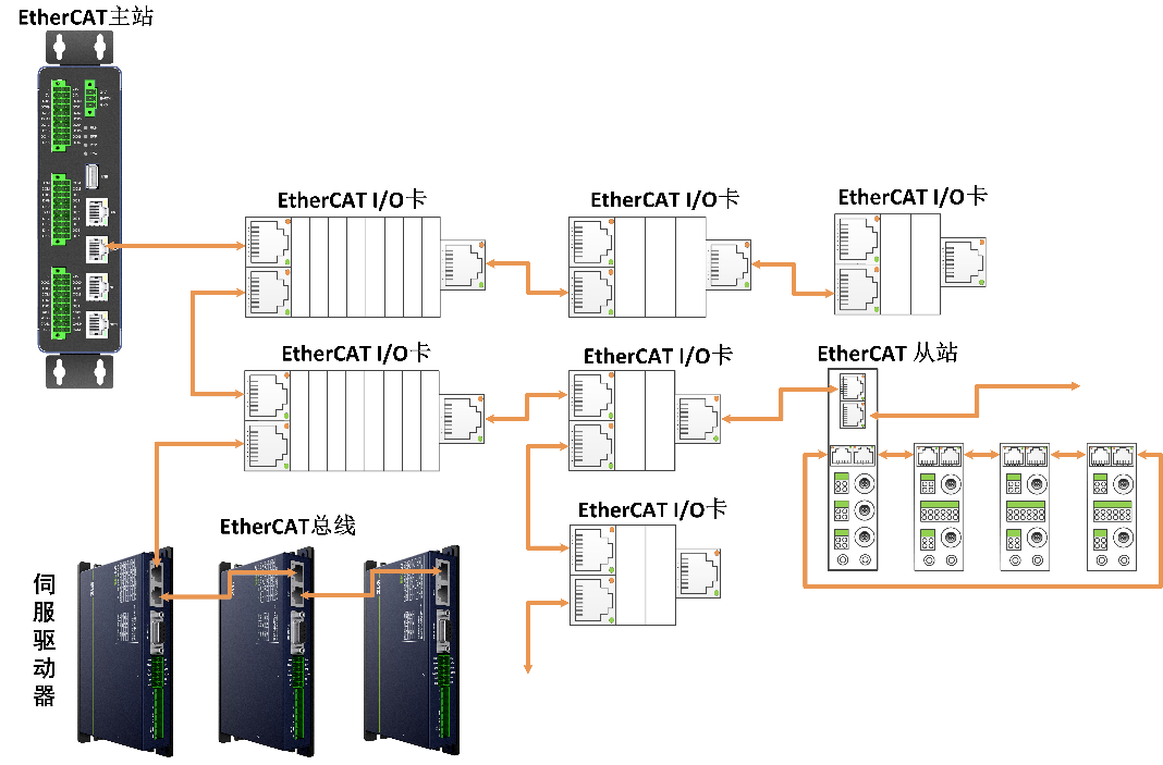
EtherCAT complies with Ethernet standards and supports various topologies: linear, star, tree, propagating in a “logical closed loop” manner, providing greater flexibility. The master station only requires a standard network card without the need for switches or routers, solving issues such as switch latency, stack latency, and bandwidth utilization in traditional Ethernet.
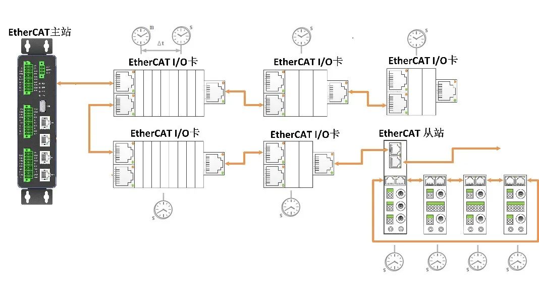
In multi-axis motion control, the precision of clock synchronization directly impacts data transmission, potentially causing frame loss and motion coordination issues, making it impossible to synchronize the execution of various axis devices. EtherCAT supports DC distributed clocks and calibrates and compensates based on hardware-generated clocks, significantly reducing system jitter.
 EtherCAT Frame Structure
Figure 4 Ethernet Frame Format Diagram
|
Name |
Meaning |
|
Destination Address |
Receiver’s MAC address. |
|
Source Address |
Sender’s MAC address. |
|
Frame Type |
0x88A4 |
|
EtherCAT Header |
Length: Total length of the message Type: 1 indicates communication with slave devices. |
|
EtherCAT Data Segment |
This segment contains the data sent by the application layer. |
|
Frame Type |
Frame Check |
 EtherCAT Application Layer
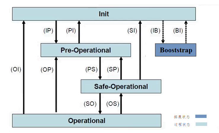
Figure 5 State Machine Transition Relationship Diagram
Table 2 EtherCAT State Machine Meaning Table
|
State |
Description |
|
Init |
No application layer communication between the master and slave, but the master can access the slave’s DL related status register information. |
|
Pre-Operation |
If the slave supports mailbox communication, the master and slave can use mailboxes and related protocols for application layer initialization and parameter configuration. No process data communication can occur in this state. |
|
Safe-Operation |
Process data communication can occur; the slave can input data, but output is not allowed, keeping the output in a “safe” state. |
|
Operation |
The slave can perform input and output operations. |
-
Broadcast Addressing broadcasts data to each slave device.
-
Incremental Addressing assigns numbers based on the order of device connections, starting from 0, decrementing by 1 for each slave.
-
Setting Addressing assigns addresses to each slave, allowing the master to find the corresponding slave for communication based on the slave address.
-
Logical Addressing provides the master with a 4G logical address space, where the FMMU maps the logical address to the physical address in the slave, allowing the master to address any data in any slave with just a logical address in the frame, which is a more flexible addressing method.
3. Data Transmission
3.1 Synchronization Manager (SM)
4.1 Description Files
The information description files mainly include EMI, ESI, and ENI files.EMI is the master station information description file;ESI is the slave description file, containing manufacturer information, device information description, SM description, object dictionary, configuration data, etc.;ENI is the EtherCAT network information configuration file, describing the number of slaves, SM and DC configuration information, etc. Together with the ESI description file, it is generated using configuration software for initializing the EtherCAT network during operation.
4.2 Configuration Software
-
Browse device information to display the master and slave device information, such as manufacturer information and network configuration details.
-
Browse topology structure to display the connection topology diagram of the master and slave.
-
FMMU/SM and DC configuration for configuring information related to FMMU, SM, PDO, and selecting the operation mode of the DC distributed clock.
-
Browse input and output variables to display PDO data input and output information, such as channel, name, type, bit length, etc.
-
Mailbox function supports configuring mailbox polling and reading object dictionary methods, displaying the related COE object dictionary list.
-
Memory information to browse memory offset information and EEPROM parameter information.
-
Integrated help documents to browse help documents, refer to more functional introductions and demo examples to assist in usage and development.
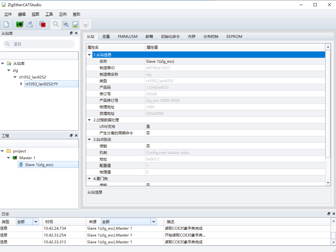
Figure 6 EtherCAT Configuration Software Main Interface
 Product Case
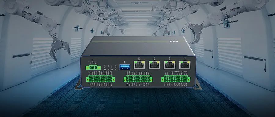
Figure7 ZMC600E EtherCAT Master Controller
1. Product Introduction
ZMC600E (Click to learn more) is the latest generation of intelligent bus-type motion controllers developed by ZLG Zhiyuan Electronics, designed for the era of factory intelligence. It adopts an advanced embedded ARM solution in the industrial field, integrating real-time operating systems and intelligent algorithms, along with industrial graphical programming software development environments.
The ZMC600E uses TI’s dual-core 64-bit Arm-Cortex-A53 and four-core Cortex-R5F AM6442 application processor as the core, with a main frequency of 1GHz, built-in 1GB DDR4, 4GB eMMC, and 32KB FRAM. It reserves multiple Ethernet, CAN, IO, USB, and other hardware interfaces. The ZMC600E supports point-to-point motion, continuous trajectory, linear and circular interpolation, continuous interpolation, spiral line motion, etc. Users can freely set running speed, stopping speed, acceleration, and deceleration times independently, smooth S-curve parameters, and support online speed and position changes, allowing users to easily build intelligent control systems and quickly implement various process applications on-site.
-
The ZMC600E integrates a commercially licensed EtherCAT master station solution;
-
The Cortex-R5F coprocessor independently processes EtherCAT data transmission, enhancing real-time performance;
-
Precise distributed clock with vibration <1μs;
-
Supports up to 128 slave nodes, with a maximum node spacing of 100m;
-
Supports CoE object read/write and SoE IDN read/write;
-
Minimum cycle period of 125μs, supporting linear, tree, and star topologies.