ADS1118 SPI Interface: An Excellent Choice for High-Precision ADC
The ADS1118 is a 16-bit high-precision analog-to-digital converter (ADC) widely used in industrial measurement, medical devices, and instrumentation. It communicates with microcontrollers via the SPI interface, providing accurate analog signal digitization. This article will explain the working principle of the ADS1118, the SPI communication method, and its applications in real projects in a straightforward manner.
1. Basic Concepts of ADS1118
The ADS1118 is a high-performance ADC chip introduced by Texas Instruments (TI). It has the following main features:
- • 16-bit resolution
- • Programmable gain amplifier (PGA)
- • Built-in temperature sensor
- • Four single-ended or two differential inputs
- • Maximum sampling rate of 860 SPS
- • SPI interface communication
This chip is like a digital “stethoscope,” capable of accurately “listening” to small changes in analog signals and converting them into digital information that microcontrollers can understand.
2. SPI Communication Principle
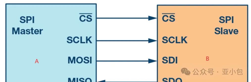
SPI (Serial Peripheral Interface) is a synchronous serial communication protocol. In the communication between the ADS1118 and the microcontroller, it acts as a “translator,” ensuring smooth information exchange between the two devices.
SPI communication uses four lines:
- • SCLK (Serial Clock): Clock signal
- • MOSI (Master Out Slave In): Master sends, slave receives
- • MISO (Master In Slave Out): Master receives, slave sends
- • CS (Chip Select): Chip select signal
Communication Process :
- 1. The microcontroller pulls the CS signal low to select the ADS1118
- 2. The microcontroller sends the control word through MOSI
- 3. The ADS1118 returns the conversion result through MISO
- 4. After communication ends, the microcontroller pulls the CS signal high
This process is like two people communicating in Morse code; one person makes ticking sounds (SCLK), while the other speaks according to the rhythm (MOSI/MISO).
3. Hardware Connection of ADS1118
Connecting the ADS1118 to a microcontroller is very simple and requires only six wires:
Microcontroller <-> ADS1118
VCC    ->  VDD
GND    ->  GND
SCK    ->  SCLK
MOSI   ->  DIN
MISO   ->  DOUT
CS     ->  CS
Precautions :
- • Ensure the power supply voltage is consistent with the datasheet (usually 3.3V or 5V)
- • The analog input signals should not exceed the chip’s supply voltage
- • During PCB layout, pay attention to the separation and proper connection of analog and digital grounds
4. SPI Communication Code Example
The following is a simplified code example for reading ADS1118 data using an STM32 microcontroller:
#define ADS1118_CS_LOW()  HAL_GPIO_WritePin(GPIOA, GPIO_PIN_4, GPIO_PIN_RESET)
#define ADS1118_CS_HIGH() HAL_GPIO_WritePin(GPIOA, GPIO_PIN_4, GPIO_PIN_SET)

uint16_t ADS1118_ReadADC(void)
{
    uint16_t config = 0x8583;  // Single conversion, channel A0, 2.048V range
    uint16_t result = 0;

    ADS1118_CS_LOW();

    HAL_SPI_TransmitReceive(&hspi1, (uint8_t*)&config, (uint8_t*)&result, 2, 100);

    ADS1118_CS_HIGH();

    HAL_Delay(10);  // Wait for conversion to complete

    ADS1118_CS_LOW();

    HAL_SPI_TransmitReceive(&hspi1, (uint8_t*)&config, (uint8_t*)&result, 2, 100);

    ADS1118_CS_HIGH();

    return result;
}
This code is like issuing a “measurement command” to the ADS1118 and patiently waiting for it to complete its work before retrieving the measurement result.
5. Practical Application Cases
Suppose we want to design a high-precision electronic scale. The ADS1118 can be used to read the small voltage changes from a strain gauge:
- 1. Connect the strain gauge to the differential input of the ADS1118
- 2. Configure the ADS1118 for low noise mode, using maximum gain
- 3. Periodically read the ADC values
- 4. Convert the ADC values to weight using calibration formulas
float ReadWeight(void){uint16_t adcValue = ADS1118_ReadADC();float voltage = (float)adcValue * 2.048 / 32768; // 2.048V rangefloat weight = (voltage – OFFSET) * SCALE_FACTOR;return weight;}
Note :In practical applications, zero-point calibration and full-scale calibration are needed to obtain accurate OFFSET and SCALE_FACTOR values.
6. Common Problems and Solutions
- 1. Unstable readings
- • Check for power supply ripple
- 2. Communication errors
- • Increase digital filtering
- • Consider using differential inputs to cancel common-mode noise
- 3. Insufficient measurement accuracy
- • Ensure correct operation of the CS signal
- • Verify the SPI mode configuration (CPOL and CPHA)
- • Extend sampling time
- • Consider using an external reference voltage source
Conclusion
The ADS1118 is a powerful ADC chip that can be easily integrated with microcontrollers via the SPI interface. Mastering its working principles and usage methods can significantly enhance high-precision analog signal acquisition applications. In practical applications, special attention should be paid to anti-interference measures and the design of signal conditioning circuits to fully leverage the performance of the ADS1118.
Practical Advice :Build a simple ADS1118 test circuit and try reading different types of sensor signals, such as thermocouples, RTDs, or strain gauges. Deepen your understanding of ADC and SPI communication through hands-on experience. During use, frequently refer to the datasheet and pay attention to how different configurations affect measurement results.