Hello everyone, in this article we will talk about a common communication protocol in embedded development – the SPI protocol.
However, today we will not discuss its basic principles, but rather explore a detail that many may not have noticed: the 4-wire and 7-wire versions of the SPI protocol.
You might wonder, isn’t SPI just those common 4 wires? Why is there a distinction between 4-wire and 7-wire? Don’t worry, keep reading, and I’ll uncover this mystery for you.
Standard SPI Protocol
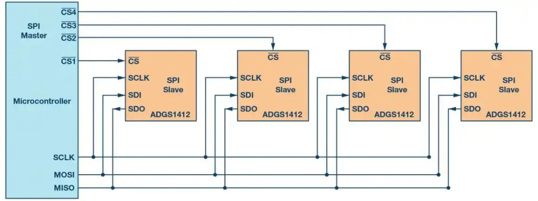
In a 4-wire SPI, the driver typically configures four main signal lines:
- MOSI (Master Out Slave In): The master device writes data to the slave device.
- MISO (Master In Slave Out): The slave device writes data to the master device.
- SCLK (Serial Clock): The master generates a clock signal to control the data transmission rate.
- CS (Chip Select): The master selects the slave device for communication.
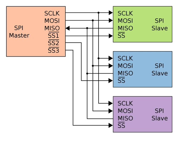
Characteristics of the SPI protocol include:
-
Full-Duplex Communication: The master device sends data to the slave device via the MOSI line while simultaneously receiving data through the MISO line. Even if the slave does not send data, the MISO line may still generate noise or invalid data, but the master will still read this data on the clock edge.
-
Point-to-Point Connection: Each slave device has an independent chip select line, and the master selects which slave device to communicate with by controlling the chip select line, thus supporting point-to-point connections.
-
Synchronous Transmission: Data transmission occurs under the control of the clock signal, which is generated by the master device to synchronize the data transmission rates of the master and slave devices.
-
Low Overhead: The SPI bus only requires four wires, which is relatively low compared to other serial communication protocols like I2C and UART.
The SPI protocol is widely used in many embedded systems and digital systems due to its simple and efficient characteristics, making it one of the commonly used interfaces for connecting peripheral devices.
What is 7-Wire SPI?
If you’ve made it this far, you must be wondering: “Isn’t 4 wires enough? Why add 3 more wires?”
In fact, 7-wire SPI is not needed in all situations; it is only used in some more complex application scenarios. So what are these additional 3 wires?
-
SDO (Slave Data Out): SDO is the data output channel from the slave device. In certain special cases, both SDO and MISO can exist simultaneously to achieve more efficient bidirectional data transmission. Simply put, if your SPI communication needs to send and receive data simultaneously in both directions, SDO comes into play.
-
SDI (Slave Data In): Opposite to SDO, SDI is the data input channel for the slave device. It is similar to MOSI but is usually used as an independent input signal line to support more complex communications.
-
IRQ (Interrupt Request): IRQ is an interrupt request signal, typically used for the slave device to actively notify the master device of certain events. For example, when data is ready, or the device needs the master to process certain states. This signal line is very useful in applications requiring real-time response, allowing the master device to respond quickly without constantly polling for data, saving a lot of time and computational resources.
Of course, these three pins may have different names on different platforms, but their functions are the same.
Advantages of 7-Wire SPI
After introducing the 7-wire SPI protocol, what advantages does it offer? Why add 3 more lines? In fact, the addition of these signal lines is to provide more control capabilities and higher performance, especially in the following areas:
-
Increased Data Transmission Rate: 7-wire SPI avoids data conflicts and blocking through independent input and output signals. Especially with the introduction of SDO and SDI, bidirectional data transmission can occur simultaneously, enhancing overall data throughput.
-
Interrupt Notifications Improve Response Speed: The addition of the IRQ signal line allows the slave device to promptly notify the master device of certain important events, avoiding the master device continuously polling the status of the peripherals, saving computational resources and wait time. Thus, the system’s response speed becomes faster.
-
Stronger Device Control Capabilities: The 7-wire SPI protocol, by adding extra signal lines, enables the master device to exert more detailed control over the peripherals, such as real-time status retrieval or more flexible management of data transmission processes. This can bring higher stability and scalability in complex embedded applications.
7-Wire SPI Transmission Process
Here, I will briefly introduce the implementation idea of the 7-wire SPI protocol driver used in my current project. The three signal lines in my project are named IND, ACK, and RDY, and the logic for their usage is as follows:
Master Sends Message to Slave:
Step 1: The master pulls the IND line, which serves as an interrupt for the slave, indicating that the master is telling the slave to prepare for data transmission.
Step 2: If the slave is ready, it will pull the RDY (ready) GPIO line, which acts as an interrupt signal for the master, notifying the master that the slave is ready to receive the message.
Step 3: If the master detects the interrupt on the RDY line, it needs to provide the clock and CS signals. If the master does not provide the clock and CS (within 2 seconds), the slave will trigger a timeout.
Step 4: If the master provides the clock and CS, data transmission can begin; there’s nothing more to say, just send whatever you have, this part follows the standard SPI protocol and requires no further analysis.
Step 5: After the slave successfully receives the data sent by the master and stores it in the buffer, it will send an ACK signal back to the master to notify that it has received the data.
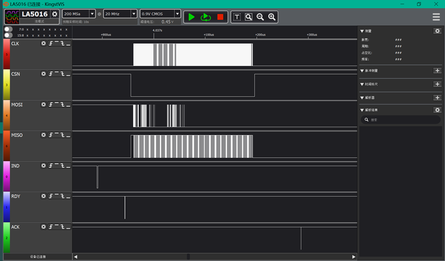
This is the complete process of one frame of SPI message. Of course, in the 7-wire SPI protocol, many more logics will be added to ensure high-speed and stable transmission. Next, let’s look at how the slave sends a message to the master.
Slave Sends Message to Master:
Step 1: The slave triggers a RDY signal, telling the master, “I am going to start sending data, please provide CS and clock quickly; if you do not do so within 2 seconds, I will timeout.”
Step 2: After the master receives the RDY signal, it starts providing the CS and clock signals. If the master does not provide CS and clock, the slave will print a timeout message.
Step 3: The slave begins to send data according to the standard SPI protocol.
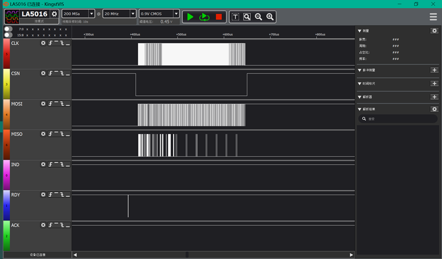
Sending messages from the slave to the master is relatively simple, so I won’t analyze it further. Now let’s briefly analyze how the master sends messages to the slave and how the slave’s driver code should be implemented.
7-Wire SPI Protocol Slave Driver
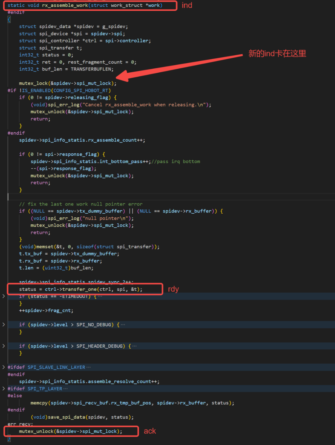
To implement a 7-wire SPI driver, we first need to configure 3 GPIOs in the device tree, namely IND, ACK, and RDY. As the slave, we need to set IND as an interrupt to notify the slave when the master starts the SPI transmission.
Register the interrupt service function for the IND pin, and in this interrupt service function, the following tasks need to be completed:
- Allocate a buffer to store the data;
- Check if the device status is normal;
- Check if data transmission is currently ongoing. If it is, wait or exit (frame-by-frame reception);
- Set the RDY pin to notify the master of its status;
- Call the reception interface in the standard SPI driver to start data transmission;
- After transmission is complete, process the data, such as serialization, storing it in a linked list, etc.;
- After transmission is complete and verification is successful, set the ACK pin to indicate that it has correctly received the data.
Of course, when designing the SPI driver in practice, there are more considerations, such as handling abnormal data, retransmission logic, etc.
Additionally, consider using memory pools or DMA buffer management to ensure efficient resource utilization. For high-frequency transmission, avoid frequent memory allocation and release.
Confirm the order of data reception and transmission to avoid data disorder or loss during processing. You can also add data verification mechanisms (like CRC checks or checksums) to ensure the integrity and correctness of the transmitted data upon reception.
Depending on the actual application scenario, consider how to handle data after transmission is complete. If data needs further processing, such as deserialization or batch transmission, it is best to design an efficient processing method in advance.
Lastly, ensure that the operations of the RDY and ACK pins are synchronized with the master device to avoid race conditions; it may be necessary to consider locking or queue management for these signals to prevent conflicts caused by multiple signals being modified simultaneously.
Conclusion
By analyzing from the perspective of the driver, there are significant differences between the 4-wire and 7-wire versions of the SPI protocol in terms of implementation and usage. The 4-wire SPI is suitable for simple, low-speed data exchanges, with a relatively straightforward driver implementation.
On the other hand, the 7-wire SPI introduces more signal lines, supports interrupt notifications, and has a more complex driver implementation, suitable for efficient, real-time communication needs.
When developing complex embedded systems, the choice between 4-wire and 7-wire SPI should be based on specific performance requirements and hardware resources.