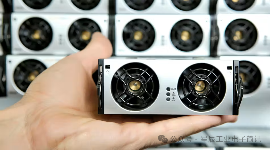
ROHM Semiconductor has developed a new reference design that uses a single microcontroller (MCU) to simultaneously control both sides of an AC-DC power supply, namely the power factor correction (PFC) AC-DC converter stage and the flyback DC-DC converter stage. ROHM states that by using a single controller to support two power stages, it can reduce costs and save power at the system level.
The REF67004 is the latest product utilizing the company’s LogiCoA architecture, which combines the advantages of analog and digital control. This reference design integrates a digital managed power circuit based on the LogiCoA MCU with an analog control power stage circuit featuring silicon MOSFETs and gate driver ICs. The power supply uses critical conduction mode (CCM) PFC to convert AC input to DC and employs a flyback converter to convert the DC bus voltage to a regulated 24V DC output.
This reference design was released about a year after ROHM launched the DC-DC buck converter reference design REF66009, enabling engineers to evaluate the new LogiCoA power architecture.
What is the difference between digital and analog power control?
In fully digital power supplies, the digital controller must accurately measure current, voltage, and other output characteristics, then compare them with reference values. The CPU or DSP uses feedback to determine the optimal pulse width modulation (PWM) waveform to control the switching of power FETs and provide the desired output. The controller must execute these calculations quickly so that the power control algorithm can respond to changing loads and thermal or other external conditions. Digital control can achieve flexibility and precise control. High-speed CPUs and DSPs can monitor and control parameters such as voltage and current accurately, improving power supply efficiency and system reliability.
Digital control also enables more advanced features, such as custom parameter settings and diagnostics, which are difficult to achieve with analog control. However, digital controllers tend to be costly and consume relatively more power, posing challenges for power supply designers (Figure 1).
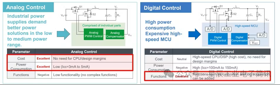
Figure 1. Advantages and disadvantages of fully analog and fully digital control in switch-mode power supplies.
Digital control in switch-mode power supplies has firmly established itself across all fields, from electric vehicle (EV) onboard chargers (OBC) to power supply units (PSU) for data centers outputting thousands of watts. However, apart from high-end power circuits and DC-DC converters that require very fast response times and fine-grained control of power operation, digital controllers are relatively rare in designs outputting tens to hundreds of watts.
ROHM states that in these cases, it is preferable to use analog controllers to output PWM signals, employing analog compensators to smooth out any undesirable fluctuations in the control loop, along with other non-digital building blocks. For DC-DC converters, the control loop can be characterized by frequency response. Frequency response affects the accuracy, stability, and transient response time of the switching regulator, which in turn affects how closely it can maintain the set output voltage under variations in input voltage, load, and duty cycle.
Whether assembled from analog devices or running in a digital controller, compensators can adjust the control loop bandwidth and customize frequency response. It also determines how the power supply operates.
Despite lacking the same level of flexibility and reliability, analog control stands out due to its simplicity. ROHM states that due to its continuous analog feedback, this technology can provide fast response times and high stability. However, while they can also avoid the costs, power consumption, and complexity associated with digital control, pure analog configurations often struggle to operate efficiently under varying load conditions and input voltages.
LogiCoA MCU: The Digital Control Center of Power Supplies
The LogiCoA solution bridges the gap between analog and digital control, with ROHM claiming it can provide the same functionality as fully digital power supplies while maintaining power consumption and costs similar to analog designs. The company states that the new REF67004 is particularly suitable for integration into consumer and industrial power supplies with output ranges from 50W to 1kW, which is the domain of analog control.
The LogiCoA MCU acts as the digital control center of the power supply. It is paired with a separate analog compensator, which consists of silicon MOSFETs and other analog and power devices, including operational amplifiers and current sensors. In digital control systems, feedback control often requires extensive calculations, and the analog comparator in the MCU and the analog compensator on the PCB facilitate this feedback control (Figure 2).
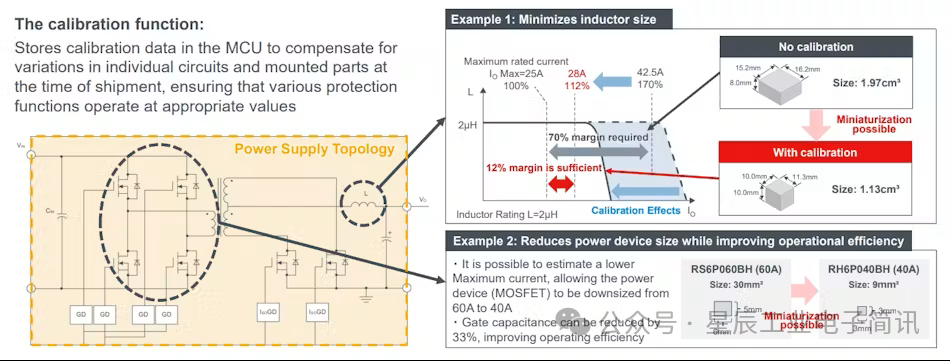
Figure 2. LogiCoA provides fully digital control by leveraging both analog and digital technologies.
“Innovations in power devices such as GaN and SiC are crucial for improving power density. However, it is equally important to have drivers and controllers that can fully utilize the capabilities of these devices. Additionally, safety and diagnostic features are essential for digital power control. LogiCoA stands out because it can flexibly adapt to these innovations through software without the need for constant development of new MCUs.” — Kenichi Morioka, ROHM Product Marketing Manager
The MCU is based on a 16-bit RISC CPU core with a maximum clock frequency of 16 MHz. LogiCoA also utilizes a 12-bit analog-to-digital converter (ADC) to convert output voltage into digital values so that the control loop can adjust accordingly, and employs an 8-bit digital-to-analog converter (DAC) to convert the desired output voltage from the digital control system into an analog signal to set the output of the power supply. One of its core building blocks is a high-resolution 16-bit PWM controller. The timer provides stricter control over the PWM signal that determines output power by varying the on and off times of the power MOSFETs.
As ROHM Product Marketing Manager Kenichi Morioka stated, “The PWM controller can dynamically adjust based on signals from the comparator in the MCU. Thus, the switching actions can be executed independently of the CPU, allowing for the use of less powerful CPUs while reducing costs. This also enables it to adapt to various power supply topologies.”
LogiCoA also features calibration capabilities to compensate for variations in external component characteristics, enabling it to handle high-precision voltage configurations and overcurrent protection (Figure 3). In turn, this reduces design margins, allowing for the selection of more compact power devices and passive components (such as capacitors and inductors), thereby saving space and lowering system-level costs.
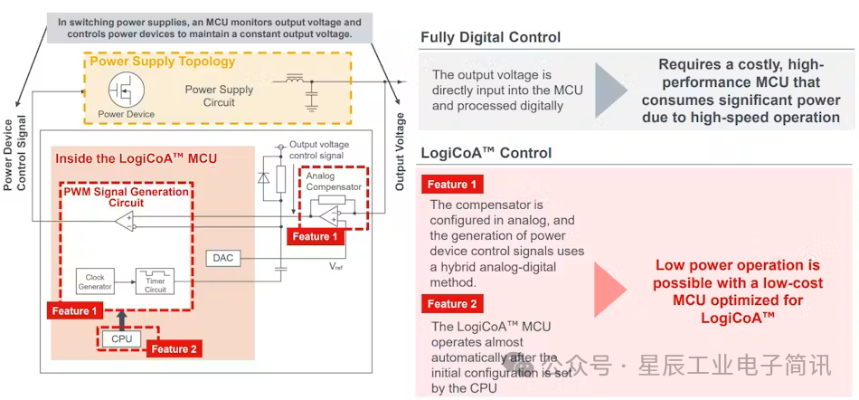
Figure 3. One of the key features of LogiCoA technology is its built-in calibration capability.
This technology adds data logging, storing input and output voltages, currents, temperatures, pre-shutdown system states, total operating time, and other parameters of the power supply. Additionally, it can use this data to identify the root cause of power supply failures or faults. Furthermore, various power control parameters and details related to power operation can be configured using ROHM’s RMOS power control system running on the LogiCoA MCU.