The power-on sequence of an MCU (Microcontroller Unit) is a carefully designed sequence that ensures the chip reliably transitions from a completely powered-off state to normal operating conditions.
1. Power-on Reset
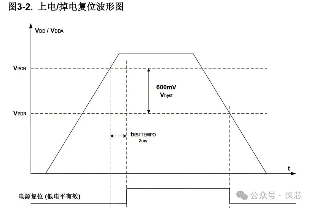
When power is applied to the MCU, the supply voltage rises from 0V to the rated operating voltage (e.g., 3.3V). The internal reset circuit of the MCU monitors the voltage changes, ensuring that the reset signal is only released when the voltage is stable, preventing erroneous CPU operations due to voltage fluctuations. The reset signal places the MCU in a known initial state:
-
Register Initialization: All CPU registers (including the Program Counter PC and Stack Pointer SP) and Special Function Registers (SFR) are reset to default values (usually 0).
-
Program Counter Setup: The PC is set to a specific reset vector address (for example, many ARM Cortex-M chips use 0x00000000, while the STM32 series may use 0x8000000).
2. Boot Mode Selection
After the MCU resets, it determines where to load the program based on the state of specific boot pins (such as BOOT0 and BOOT1 on STM32). Common boot modes include:
-
Boot from Main Flash: The most commonly used mode, executing the user-programmed application.
-
Boot from System Memory: Typically contains a factory pre-installed Bootloader for serial programming, etc.
-
Boot from SRAM: Usually used during the debugging phase, where code is lost on power down.
3. Load Vector Table
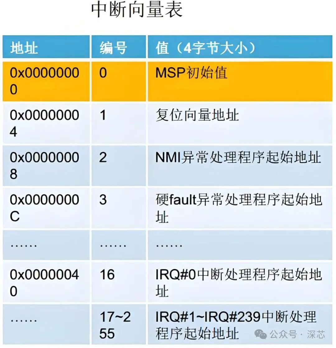
The CPU retrieves the interrupt vector table from the starting address specified by the boot medium (reset vector address). The vector table is an array that stores the entry addresses of exception handlers, with the two most critical entries being:
-
Initial Stack Pointer (MSP): The first entry of the vector table, which the CPU loads into the main stack pointer register, establishing stack space for subsequent function calls and interrupt handling.
-
Reset Vector: The second entry of the vector table, pointing to the entry address of the reset interrupt service routine (Reset_Handler). The CPU jumps to this address for execution.
4. Execute Reset Interrupt Service Routine
Reset_Handler is the first piece of code executed after the MCU powers on, typically provided by the chip manufacturer in the startup file (e.g., startup.s). It is responsible for setting up the most basic software and hardware environment:
-
Memory Initialization:
-
Copy initialized global variables (.data section) from Flash to RAM (since RAM is faster for read/write operations).
-
Zero out uninitialized global variables (.bss section) to prevent the use of random values.
-
System Initialization:
-
Disable Interrupts (cpsid i): Prevent interruptions during the initialization process.
-
Initialize Clock System: Configure the core clock, main clock, and peripheral clocks.
-
Disable Watchdog: Prevent the watchdog from timing out and causing a reset during lengthy initialization.
-
Configure Interrupt Vector Table: Set its location (Flash or RAM) and offset.
-
Initialize Stack: Set up the heap and stack for the C language environment.
5. Jump to Main Program
Once all initialization tasks are complete, Reset_Handler calls or jumps to the entry function of the C library (e.g., __main), which ultimately jumps to the user’s main() function, and the MCU officially begins executing the user application.
The power-on process of the MCU is a finely ordered initialization sequence from hardware to software, from low-level to high-level, ensuring that the chip can reliably run your code from a defined state. Understanding this process aids in low-level driver development, system debugging, and performance optimization.