1
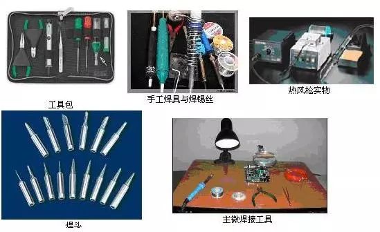
Tools for Manual Soldering
Any electronic product, from a rectifier made up of a few components to a computer system composed of thousands of parts, is constituted by basic electronic components and functions, connected according to circuit principles using specific techniques.Although there are various connection methods (e.g., wrapping, crimping, adhesive), the most widely used method is soldering.
Tools for Manual Soldering
-
Electric Soldering Iron
-
Chrome Iron Stand
Conditions for Soldering
-
The workpiece must have solderability.
-
The surface of the soldered metal should be kept clean.
-
Use appropriate flux.
-
Maintain an appropriate soldering temperature.
-
Ensure suitable soldering time.
2
Solder and Flux
Common Solder Materials
-
Tubular Solder Wire
-
Oxidation-Resistant Solder
-
Silver-Containing Solder
-
Solder Paste
Selection of Flux
During the soldering process, a thin layer of oxide film forms on the metal due to heating, which hinders the wetting of solder and affects the formation of solder joint alloys, easily leading to cold solder joints or false soldering.
Using flux can improve soldering performance. Fluxes include rosin, rosin solutions, solder paste, and solder oil, and should be selected appropriately based on different soldering objects. Solder paste and solder oil can be corrosive and should not be used for soldering electronic components and circuit boards. After soldering, any residue of solder paste or oil should be cleaned off. When tinning component leads, rosin should be used as flux. If the printed circuit board is already coated with a rosin solution, there is no need to use additional flux when soldering components.
3
Precautions for Manual Soldering
Manual soldering skills are fundamental, as maintenance and repair must also utilize manual soldering in large-scale production.Therefore, proficiency can only be achieved through learning and practical operation.The precautions are as follows:
Correct Grip of the Soldering Iron
Gripping the soldering iron correctly ensures the operator’s physical and mental health, reducing the risk of labor injuries.To reduce the inhalation of harmful gases emitted when the flux is heated, the distance from the iron to the nose should generally be no less than 20cm, preferably around 30cm.
There are three ways to hold the soldering iron, as shown in the figure below.
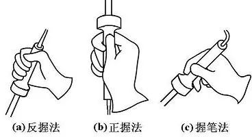 Grip Methods for the Electric Soldering Iron
The reverse grip method is stable and less tiring for long operations, suitable for high-power soldering iron; the forward grip method is suitable for low-power soldering iron or bent soldering iron; generally, the pencil grip is used when soldering printed circuit boards or similar workpieces.
Correct Grip of Solder Wire
Solder wire generally has two methods of holding, as shown in the figure below.Since solder wire contains a certain proportion of lead, which is a harmful heavy metal to the human body, gloves should be worn during operation or hands should be washed after use to avoid lead dust ingestion.
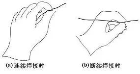 Methods of Holding Solder Wire
After using the electric soldering iron, it must be placed securely on the iron stand, ensuring that wires and other debris do not touch the iron tip to prevent burns or electrical leakage.
4
Basic Steps of Manual Soldering Operation
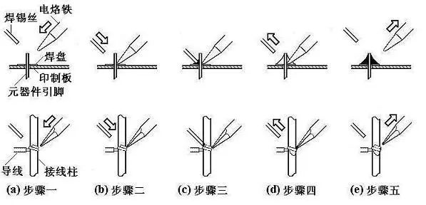
Mastering the temperature of the soldering iron and soldering time, selecting the appropriate soldering tip and contact position for the solder joint is crucial for achieving good solder joints. The correct manual soldering process can be divided into five steps, as shown in the figure.
 Steps of Manual Soldering
Basic Operating Steps
-
Prepare for Soldering (Figure (a)): Hold the solder wire in the left hand and the soldering iron in the right hand, entering the preparation state. The soldering iron tip should be kept clean, free from solder dross and oxidation, and coated with a layer of solder.
-
Heat the Workpiece (Figure (b)): The soldering iron tip is placed at the joint of the two workpieces, heating the entire workpiece for about 1 to 2 seconds. When soldering components on a printed circuit board, ensure that the soldering iron tip simultaneously contacts both soldered items, such as the wire and terminal, or the component lead and pad, for even heating.
-
Feed in Solder Wire (Figure (c)): When the soldering surface is heated to a certain temperature, feed the solder wire from the opposite side of the soldering iron to the workpiece. (Note: Do not place the solder wire directly on the soldering iron tip.)
-
Remove the Solder Wire (Figure (d)): After a sufficient amount of solder has melted, immediately move the solder wire away at a 45° angle upwards.
-
Remove the Soldering Iron (Figure (e)): Once the solder has wetted the pad and the soldering area of the workpiece, remove the soldering iron at a 45° angle upwards to finish soldering. The time from the third step to the fifth step should also be about 1 to 2 seconds.
5
Specific Techniques for Manual Soldering
While ensuring high-quality solder joints, specific soldering techniques may vary, but the following methods summarized by predecessors are invaluable for beginners.
Keep the Soldering Iron Tip Clean
During soldering, the soldering iron tip is in a high-temperature state for extended periods and comes into contact with flux and other weakly acidic substances, making it prone to oxidation and corrosion, accumulating a layer of black impurities.These impurities form an insulating layer that hinders heat transfer between the soldering iron tip and the workpiece.Therefore, it is essential to wipe the soldering iron tip with a damp cloth or wet wooden fiber sponge regularly.For ordinary soldering iron tips, a file can be used to remove the oxidized layer when heavily contaminated.However, this method should never be used for long-life soldering iron tips.
Increase Contact Area to Speed Up Heat Transfer
During heating, ensure that all parts of the workpiece needing solder are evenly heated, rather than just heating one part. Avoid applying pressure with the soldering iron to the workpiece to prevent damage or unnoticed hazards.Some beginners mistakenly apply pressure with the soldering iron tip to speed up soldering, which is incorrect.The correct method is to select different soldering iron tips based on the shape of the workpiece or to modify the soldering iron tip to ensure surface contact with the workpiece rather than point or line contact.This significantly improves heat transfer efficiency.
Heating Should Rely on Solder Bridge
In non-assembly line operations, solder joint shapes can vary widely, making it impractical to constantly change soldering iron tips.To improve heating efficiency, a solder bridge is needed for thermal transfer.A solder bridge refers to retaining a small amount of solder on the soldering iron tip, serving as a thermal bridge between the soldering iron tip and the workpiece during heating.Since molten metal has a much higher thermal conductivity than air, it quickly heats the workpiece to soldering temperature.It is important to note that the amount of solder retained as a solder bridge should not be excessive, as prolonged retention at high temperatures can degrade its quality and potentially cause unintended short circuits between solder joints.
Careful Removal of the Soldering Iron
The removal of the soldering iron should be timely, and the angle and direction of removal are related to the formation of the solder joint.The figure shows the effect of different removal directions of the soldering iron on the amount of solder at the joint.
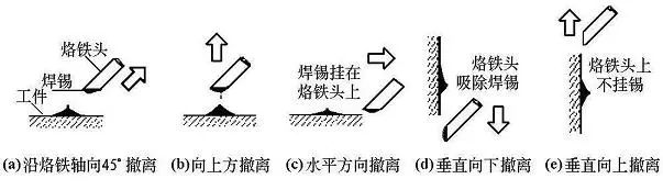 Relationship Between Soldering Iron Removal Direction and Solder Amount
Do Not Move Before the Solder Solidifies
Do not move or vibrate the workpiece, especially when holding it with tweezers; wait until the solder solidifies before removing the tweezers, or it may easily cause a loose or cold solder joint.
Moderate Amount of Solder
Tubular solder wire commonly used in manual soldering already contains flux made from rosin and activator.The diameter of solder wire ranges from 0.5 to 5.0mm, and should be selected based on the size of the solder joint.Generally, the diameter of the solder wire should be slightly smaller than that of the pad.
As shown in the figure, excessive solder not only unnecessarily consumes solder but also increases soldering time and reduces work speed. More seriously, excess solder can easily cause unnoticed short circuit failures. Conversely, insufficient solder cannot form a strong bond, which is also detrimental. This is particularly critical when soldering leads on printed circuit boards, as insufficient solder can easily lead to lead detachment.
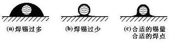
Control of Solder Amount
Moderate Amount of Flux
A proper amount of flux is very beneficial for soldering.Excessive use of rosin flux requires cleaning up the excess after soldering and prolongs heating time, reducing work efficiency.When heating time is insufficient, it can easily lead to defects like “slag inclusion.”When soldering switches and connectors, excess flux can flow onto contacts, causing poor connections.
The appropriate amount of flux should only wet the areas to be soldered without flowing through the vias on the printed circuit board. For soldering with rosin-core solder wire, there is generally no need to apply additional flux. Currently, most printed circuit board manufacturers apply a rosin spray treatment before the boards leave the factory, eliminating the need for additional flux.
Do Not Use the Soldering Iron Tip to Transport Solder
Some people have a habit of soldering directly on the soldering surface, which leads to oxidation of the solder.Since the temperature of the soldering iron tip is generally above 300°C, the flux in the solder wire easily decomposes and fails at high temperatures, and the solder is in an overheated, low-quality state.It is particularly important to note that some outdated publications have introduced the method of using the soldering iron tip to transport solder; readers should be cautious in differentiating.
6
Solder Joint Quality and Inspection
The quality requirements for solder joints should include good electrical contact, strong mechanical bonding, and aesthetic appearance.The most important factor in ensuring solder joint quality is to avoid cold solder joints.
Causes and Hazards of Cold Solder Joints
Cold solder joints are primarily caused by oxides and dirt on the surface of the metal to be soldered, resulting in a connection with contact resistance, leading to unstable circuit operation with intermittent connectivity, increased noise, and significant risks in circuit debugging, usage, and maintenance.
Moreover, some cold solder joints may maintain good contact for a considerable time during the initial operation of the circuit, making them hard to detect. However, under environmental conditions like temperature, humidity, and vibration, the contact surface gradually oxidizes, leading to incomplete contact. The contact resistance of cold solder joints can cause localized heating, which exacerbates the condition of incomplete contact, potentially leading to joint detachment and complete circuit failure.
This process can last for one to two years, and its principle can be explained by the “galvanic cell” concept: when moisture infiltrates the gaps of solder joints, water molecules dissolve metal oxides and dirt to form an electrolyte, with the copper and lead-tin solder acting as the two electrodes of the galvanic cell, leading to oxidation of the lead-tin solder and reduction of copper. In such a galvanic structure, metallic corrosive loss occurs at cold solder joints, with localized heating further accelerating the chemical reaction, and mechanical vibrations expanding the gaps until a vicious cycle leads to an open circuit.
Statistics indicate that nearly half of the failures in electronic products are due to poor soldering. However, identifying the faulty cold solder joint among thousands of solder joints in an electronic device is not an easy task. Therefore, cold solder joints pose a significant reliability risk in circuits and must be strictly avoided. Extra caution is necessary during manual soldering operations.
In general, the main causes of cold solder joints include: poor solder quality; inadequate or poorly reducing flux; insufficient pre-cleaning of the soldered surface; poor tinning; incorrect soldering iron tip temperature; improper soldering time; and movement of soldered components before the solder has solidified.
Requirements for Solder Joints
-
Reliable electrical connection
-
Sufficient mechanical strength
-
Neat and tidy appearance
Typical Formation and Appearance of Solder Joints
On single-sided and double-sided (multi-layer) printed circuit boards, the formation of solder joints differs: In single-sided boards, solder joints form only above the pads on the soldering surface; In double-sided or multi-layer boards, molten solder not only wets the pads but also penetrates into the metallized holes due to capillary action, forming solder joints above the soldering pads, within the metallized holes, and on some pads on the component side, as shown in the figure.
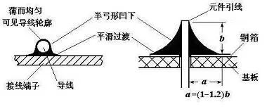 Left: Formation of Solder Joints Right: Appearance of Typical Solder Joint
As seen in the figure, the typical solder joint should have a shape resembling a cone with a slightly concave surface, tapering symmetrically from the center of the soldering wire. The surface of cold solder joints often bulges outward, making them identifiable.
On the solder joint, the solder interface should transition smoothly, with the junction of solder and workpiece as flat as possible and the contact angle minimized; the surface should be smooth and shiny, free from cracks, pinholes, or slag inclusions.