Recently, during mass production of our company’s products, we discovered several boards with abnormal boot internal information, which prevented normal booting into the APP main program. Preliminary analysis suggested that the factory production line mistakenly flashed the boot program of other products. To verify this judgment, we need to read the internal program of the chip to check if it is correct. Below, we analyze a quick and simple method to read the internal program of the chip.
1. Preliminary Preparation
First, ensure that the computer has JFlash software installed. After installation, the JLink driver will be installed by default, which includes the following tools:
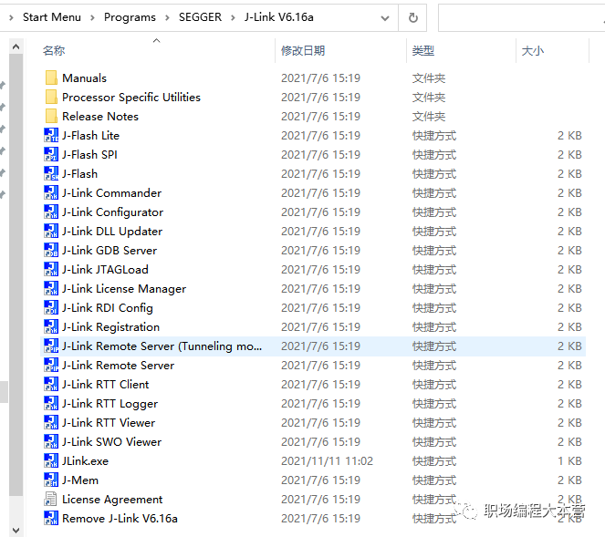
J-Flash is used for program downloading and reading. To read and download with JFlash, you need to open the software and create a new project related to the chip, which will not be elaborated here.
J-Link Commander is also used for program downloading and reading, but it operates via command line, requiring only a few cmd commands, making it very simple and convenient.
Below are the specific steps to read chip data using JLink.exe:
-
connect // Connect to the target chip
-
? // Select the corresponding chip model or core
-
Select JTAG/SWD
-
Set download speed
-
Input h to hold the core and view the core registers
-
mem address byte_count // View byte information at the corresponding address
savebin storage_location_and_name start_address length_to_read // savebin copies memory data to localmem 0x01008000 4savebin F:\testOut.bin 0x01008000 0x7000
Next, we will elaborate on the above six small steps with images.
2. Specific Steps to Read Chip Data First, double-click J-Link Commander (or JLink.exe) in the installation directory to open it, as shown in the figure below: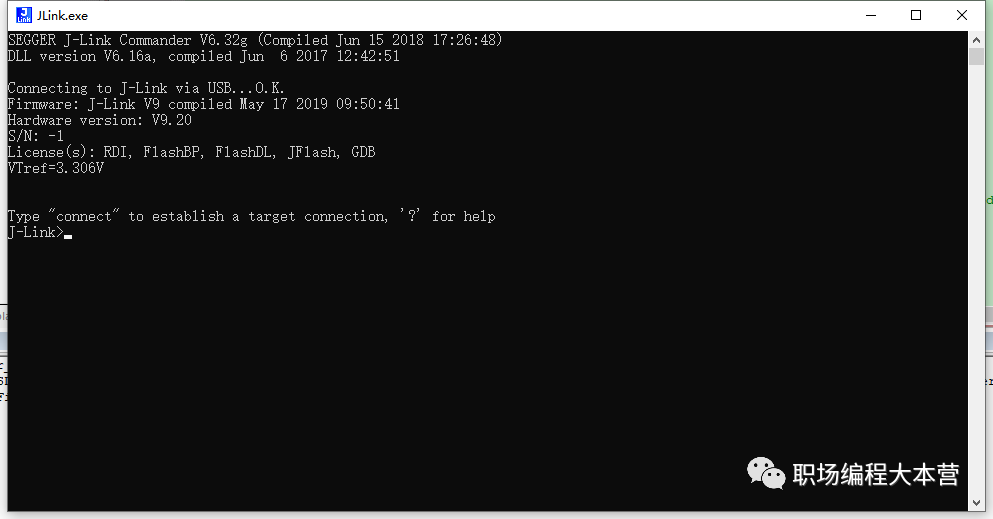 Then, connect the Jlink emulator to the MCU, either JTAG or SWD, and you can start operating via cmd commands:1. Input connect to connect to the target chip;
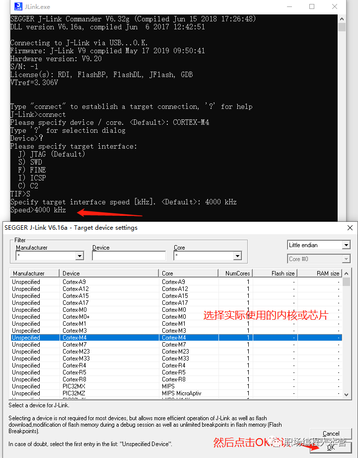
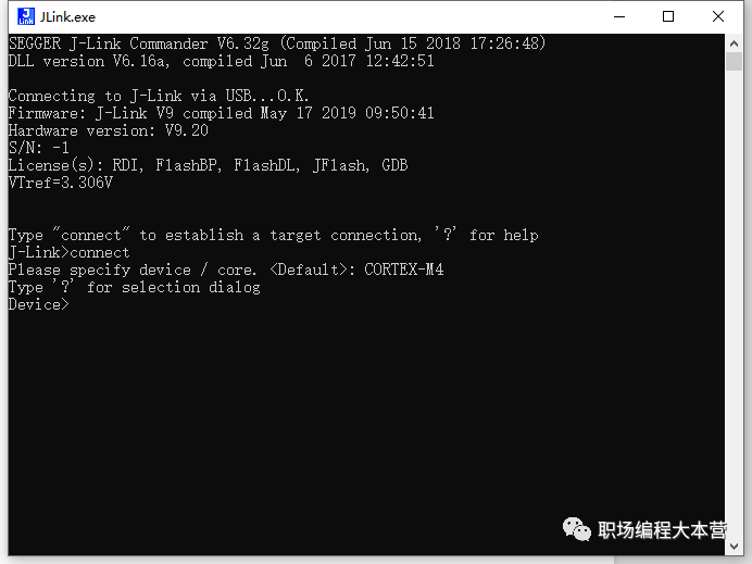 2. Input ? to select the corresponding chip model or core;3. Select the actual interface used, such as JTAG or SWD; here we take SWD as an example:
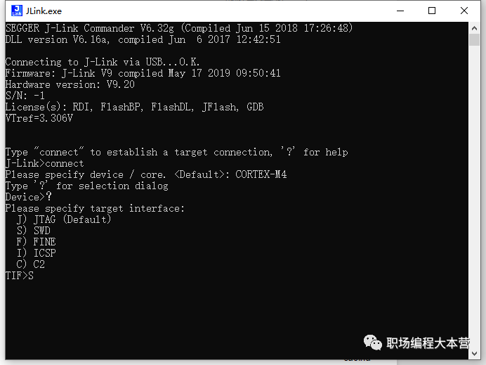
4. After confirming the interface, you will enter the ‘Speed>’ selection state. Input the actual download speed as needed, and after confirming the required speed, a window will pop up to select the core or chip, as shown in the figure below. Here we take Cortex-M4 as an example; after selecting, click OK at the bottom right.
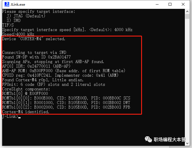
After correctly selecting the core, there will be a corresponding prompt, as shown in the figure below:
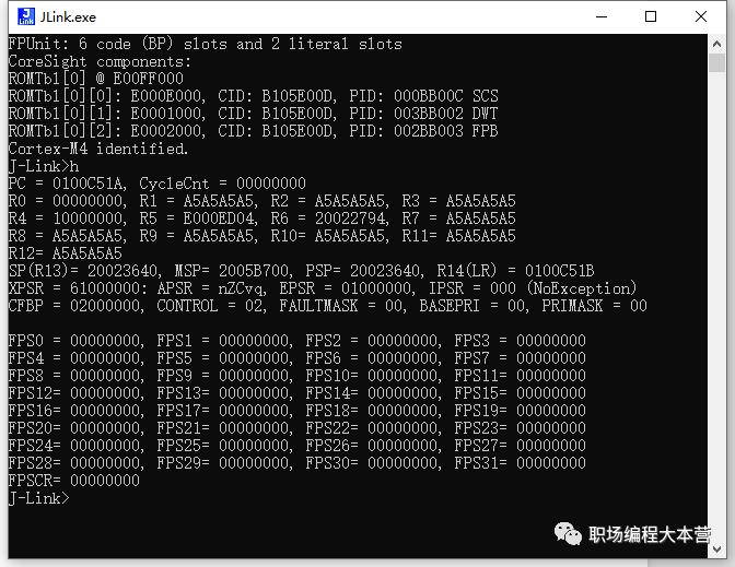
5. Input h to hold the core and view the core registers:
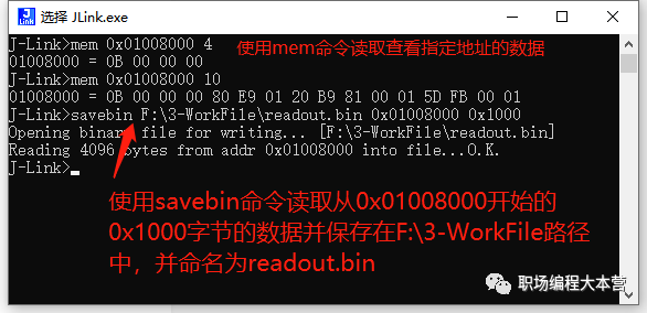
6. Use the mem command to view data at the corresponding memory address or use the savebin command to read data from a specified address of the chip,
mem address number_of_bytes_to_read
savebin save_location_and_name start_address length
3. Conclusion
By following the above simple steps, we have successfully read the internal data information of the chip. Reading registers or specific memory data without an IDE emulator is very helpful in assisting with the analysis of abnormal MCU operation.
[Follow me to learn and grow together]
If you like it, please give a “like” and “view”