What is the purpose of grounding an oscilloscope?

Grounding serves as the reference point for all voltage measurements, ensuring that there is a known 0V voltage point in the circuit. This is crucial for ensuring measurement accuracy, suppressing noise interference, and ensuring measurement safety.
It can be observed that the power cord of a desktop oscilloscope is a three-prong plug, where the third prong is connected to the ground. The ground of the desktop oscilloscope is also connected to the mains ground. The casing of the oscilloscope is likewise grounded, preventing the risk of electric shock to the user due to leakage current causing the casing to become live.
Question
What is grounding?
Grounding refers to the physical connection to the earth, typically achieved using a ground wire. Good grounding provides a safe path for current to flow.
Signal ground refers to the reference point for all signal level voltages in the circuit under test. All signal measurements are based on the signal ground. The signal ground can be connected to the earth or isolated from it in certain applications. A stable signal ground ensures that the collected signals are not affected by reference level waveform variations.
Chassis grounding usually refers to connecting to the oscilloscope’s casing, which is typically grounded through the base, protecting the oscilloscope from external electromagnetic influences and providing good safety measures.
The Principle of Grounding
For an oscilloscope, grounding means connecting the negative terminal of the device under test, the ground clip of the probe, and the oscilloscope’s ground terminal to the ground wire. When the probe’s ground clip is connected to the ground of the circuit under test, the oscilloscope’s internal ground terminal and the ground of the device under test form a system.
In any electrical measurement, a reference point is needed to understand voltage levels. When measuring the voltage of a signal, what is actually measured is the potential difference between the signal terminal and the grounding reference point. Good grounding ensures accurate voltage measurements.
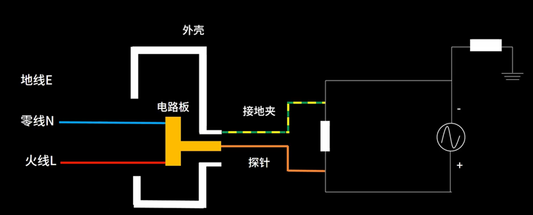
Diagram of oscilloscope probe grounding for the signal under test
Does an oscilloscope need to be grounded?
If the oscilloscope’s probe ground clip is connected to a non-true ground point, it can have serious consequences. For example, if it is connected to a signal with a potential difference, or to the neutral or live wire, it can introduce current into the oscilloscope, causing the current to trip or even damage the oscilloscope. This is one of the most common mistakes made by novice engineers when testing mains electricity.
Good grounding not only ensures measurement accuracy but also effectively reduces environmental noise interference, such as electromagnetic radiation or noise from other circuit components. These noises can superimpose on the signal, causing waveform jitter, distortion, or excessive noise, thus affecting measurement results. The following image shows a typical case: due to excessive ground noise, significant noise interference appears in the signal.
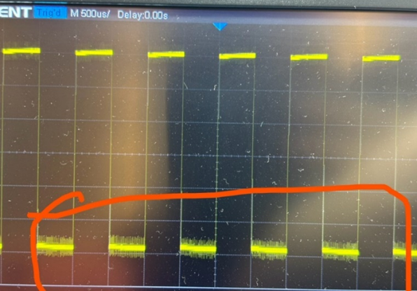
Signal noise caused by a dirty ground
When using an oscilloscope for measurements, having a dirty ground or radiation interference is one of the common problems. The following image shows a typical power frequency interference test graph, where the 50Hz power frequency interference is caused by the 50Hz sine wave interference signal from the power system.
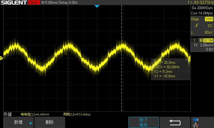
Power frequency interference
This power frequency interference can originate from various sources:
1. The probe’s feed line may act like an antenna, receiving and conducting interference signals from power frequency electromagnetic waves.
2. Ground loops may couple interference signals into the measurement system through spatial radiation.
3. Power frequency interference may also be conducted to the oscilloscope through the power line, affecting measurement results.
Power frequency interference typically has a greater impact on high-impedance device measurements, while oscilloscopes are generally used to test high-frequency low-impedance devices, so the impact of power frequency interference is usually not significant.
To avoid power frequency interference, good grounding is essential, along with reducing ground loops, turning off other electrical devices, changing the testing environment, and using filters or isolation transformers to resolve the issue.
Some users may choose to perform floating measurements to cope with dirty ground situations, but is floating measurement correct?
To make the oscilloscope float, users may cut the ground wire on the power line, but every oscilloscope manufacturer warns users against doing this in their user manuals.
Floating measurements carry the following risks:
1. Electric shock hazard: If the probe ground lead is connected to a high-voltage reference point, touching any conductive surface of the oscilloscope (including the ground lead of other probes) can result in severe electric shock.
2. Device damage: Floating measurements can damage the device under test.
3. Poor measurement accuracy: Floating measurements introduce additional noise and errors, affecting the accuracy of measurement results.
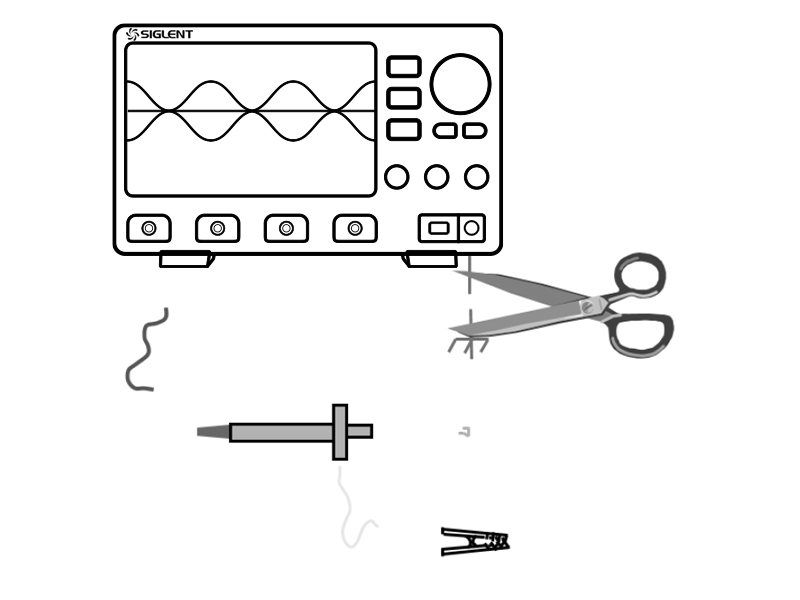
Floating measurement
Does not grounding affect the accuracy and amplitude of the test signal?
The following image shows a test using a 25MHz sine wave, measuring a peak-to-peak value of 477mV, with a peak-to-peak standard deviation of 1mV, indicating that the peak-to-peak value is relatively stable. When we remove the ground clip, we find that the measured signal peak-to-peak value is 236mV, with a peak-to-peak standard deviation of 1.19mV.
Relatively speaking, after removing the ground clip, the peak-to-peak value of the signal under test decreases, and the stability of the signal also declines, although the shape and frequency of the signal do not change significantly.
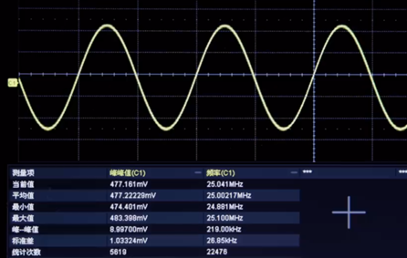
Good grounding
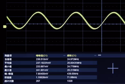
Disconnected ground wire
The following diagram shows a super simplified circuit diagram for testing the device under test. When the ground clip is connected, the probe measures the voltage difference across the resistor of the device under test. However, when we disconnect the ground clip, the oscilloscope measures the voltage difference between the positive terminal of the device under test and the ground wire. The resistance on the ground wire cannot be ignored, and at this point, we are not measuring the correct signal voltage value.
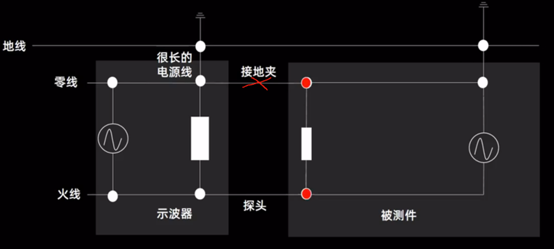
Super simplified circuit diagram for testing the device under test
How is grounding done?
Typically, when grounding an oscilloscope, the ground clip of the probe or a grounding spring is used. The ground clip is one of the accessories of the probe, usually in the form of a clip, used to connect to the signal ground to ensure an accurate and reliable measurement reference point.
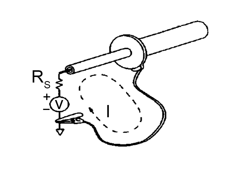
Current return loop of the probe signal
The grounding lead has an inductive reactance component; as the grounding lead gets longer, the inductance value increases, which enhances the resonance effect. The shorter the probe’s ground wire, the better; the larger the loop area between the ground wire and the signal wire, the greater the impact from radiation. The image shows the impact of different lengths of ground wires on measurements, which can introduce more than 10% error in peak-to-peak measurements.
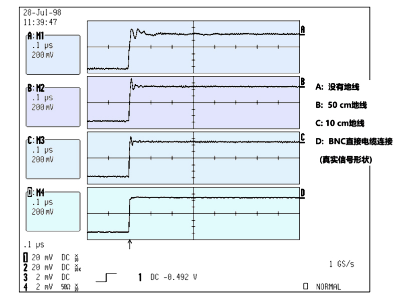
Impact of grounding lead
Some engineers, when testing multiple signals, only connect one signal ground, leaving the ground clips of the other signals floating. In this case, multiple signals will share this one current return grounding path. When multiple currents flow through this loop, it will generate significant common-mode inductance, leading to incorrect test signals.
To reduce resonance effects and minimize parasitic capacitance, we typically use grounding springs. Grounding springs are usually included in the probe accessory kit, and when used, the probe’s protective cap needs to be removed, and the grounding spring installed at the front end of the probe. Grounding springs are particularly suitable for testing in environments with densely packed components on PCB boards. Additionally, grounding springs are often used to test power ripple to ensure the accuracy and stability of measurement results.
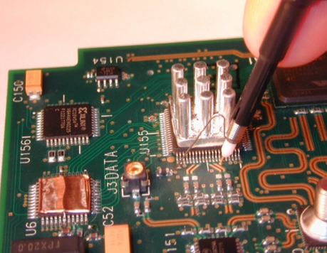
Using a grounding spring
How to test when the ground is dirty?
Here are some common solutions:
1. Use an isolated oscilloscope. For example, a handheld oscilloscope is isolated from the ground, allowing it to be used directly for testing floating signals without worrying about grounding issues.
2. Can a desktop oscilloscope operate without grounding? Yes.A desktop oscilloscope can also be isolated from the ground using an isolation transformer, thus separating the signal ground from the ground wire. In this case, a passive probe can be used to test isolated signals. For example, when testing 220V mains electricity, the signal end of the passive probe can be connected to the live wire, and the ground clip can be connected to the neutral wire for measurement. (Ordinary non-isolated oscilloscope ground clips must be connected to the ground wire, and cannot be connected to the neutral or live wire.)
3. Use a differential probe: Differential probes do not require direct grounding and can measure the voltage difference between two points in a circuit, especially suitable for situations where a common ground cannot be established. Differential probes can also effectively filter out common-mode noise, reducing signal distortion. When using, try to couple the positive and negative leads of the probe together to ensure they are subjected to balanced spatial radiation, thus better eliminating common-mode noise.
-END-
Scan to join the hardware communication group