Original contributions are welcome; the more you write, the more you earn.


What is a Flexible Circuit Board (FPCB)?
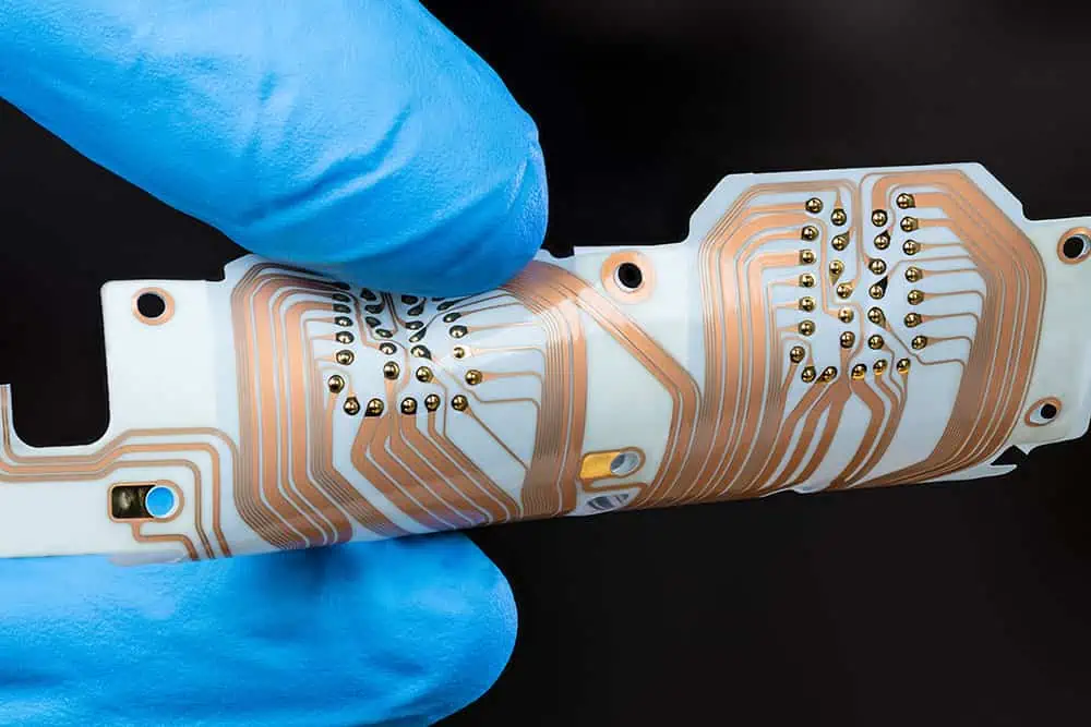
A Flexible Circuit Board (FPCB), commonly referred to as a soft board, is an abbreviation for Flex-PCB and is sometimes called FPC. FPCs and PCBs (Printed Circuit Boards) are similar in function and structure, but PCBs typically refer to rigid circuit boards.
Both FPCs and PCBs have copper foil circuits designed on their surface and inner layers for transmitting electronic signals. The main difference between them lies in the material of their substrates. The substrate of a PCB is similar to glass, making it hard and rigid, while the substrate of an FPC is similar to paper, allowing it to be soft and flexible on a flat surface.
What are the characteristics of FPC?
FPCs are characterized by being lightweight, thin, flexible, and easy to bend, which are their advantages and unique features. Therefore, they are particularly suitable for products with limited space that cannot meet all design requirements with a single rigid PCB.
Some products may require overlapping multiple PCBs to fully utilize the limited internal space, necessitating flexible FPCs for connections.
Others may use soft boards to connect distant PCBs for signal transmission to save board material, while some PCBs may need to intersect with other PCBs at vertical or different angles.
Generally, it is not suitable to design complex circuits and solder precision electronic components on FPCs because:
1. The solder used for electronic components can easily crack on the flexible FPC.
2. Compared to PCBs, FPCs are less heat-resistant. They can easily warp or delaminate at high temperatures.
3. The solder mask precision on FPCs is harder to control than on PCBs because it uses PI film (which can be thought of as a thin film similar to a plastic bag). The solder pad openings on PI film are generally punched using a die, and then the film is attached to the FPC, resulting in lower precision than the screen printing used for PCBs, making the openings prone to misalignment and unevenness.
4. FPCs are not suitable for designing multilayer copper foil circuits. As the number of copper foil layers increases, the FPC becomes stiffer, and its bending capability diminishes, which undermines the main advantage of FPCs. Additionally, to create accurate solder pads, more advanced laser technology may be required to open windows on the PI film, which will increase costs.
However, we can still see instances where precision electronic components are soldered onto FPCs, such as in digital cameras. How is this achieved?
In fact, it is not difficult to accomplish this; one only needs to attach a rigid stiffener to the back of the FPC where precision components need to be soldered. However, this means that components can only be soldered on one side of the stiffener, as it does not have any circuits and serves purely as structural support. Consequently, the cost of such FPCs is significantly higher than that of standard FPCs.
Classification of FPCs:
Single-sided board:
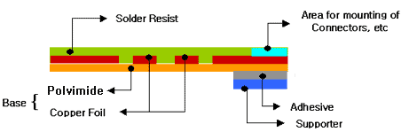
Double-sided board – single copper, double processing:
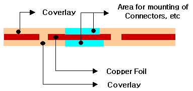
Double-sided board – double copper, double processing:
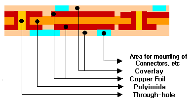
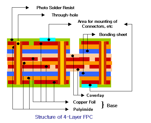
Multilayer board:
Contributor: Yao
Follow Engineer Xiao Jie for more electronic knowledge, interesting electronic facts, and electronic DIY!
/END
Past Issues Review
REVIEW
Complete Classification of PCBs: Do You Understand Them All?
The Most Comprehensive Guide to Component Soldering: From Novice to Expert!

What is the Siphon Effect of Solder Wicks? How to Prevent It?