In actual industrial automation applications, various communications are essential, such as PN communication, S7 communication, MODBUS TCP communication, and MODBUS communication, among others; however, the most widely used is MODBUS communication, as it is an open, free, and universal communication protocol. Often, during equipment debugging on the industrial site, communication failures may occur for no apparent reason, making it necessary to use a debugging tool to test potential issues. Additionally, for beginners wanting to learn MODBUS communication, debugging tools can be utilized for testing and learning without adding communication instruments.
Below, we will use the Siemens 200SMART PLC as the MODBUS master station and a debugging tool as the slave to conduct communication tests.
The communication task is shown in Figure 1.
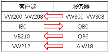
Figure 1: Data Interaction Diagram
One RS485 to USB adapter, one RS485 male connector, and two cables, as shown in Figure 2; one PC, one 200SMART, and one communication network cable. The CPU port pin description is shown in Figure 3.
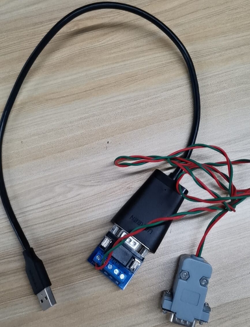
Figure 2: USB to Serial Port Hardware
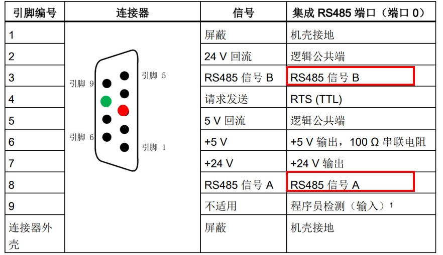
Figure 3: Serial Port Pin Description
Communication Commands: The Siemens 200SMART library commands automatically integrate MODBUS communication library commands, calling different library commands based on different ports. This example will use two master station commands; Figure 4 shows the master station initialization command, and Figure 5 shows the master station data read/write command.
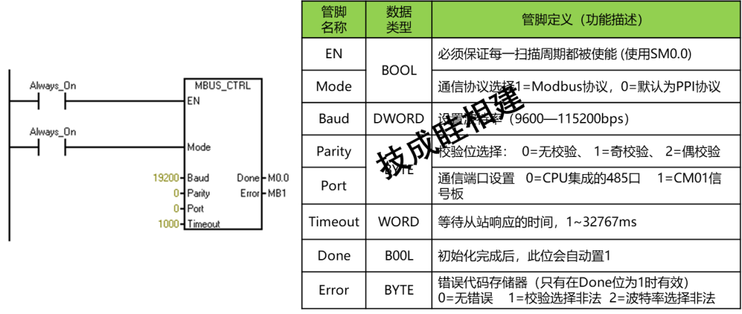
Figure 4: Master Station Initialization Command
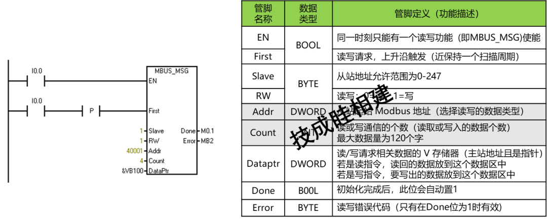
Figure 5: Master Station Data Read/Write Command
1. Call the MODBUS master station library commands for programming on the SMART side, as shown in Figures 6 and 7.
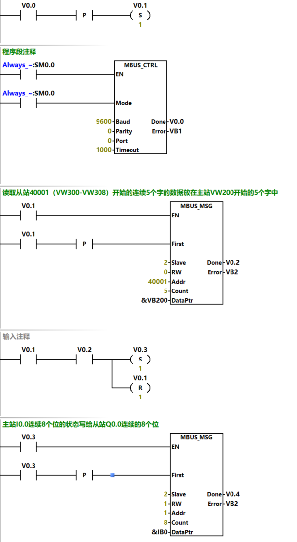
Figure 6: Master Station Data Read/Write Program
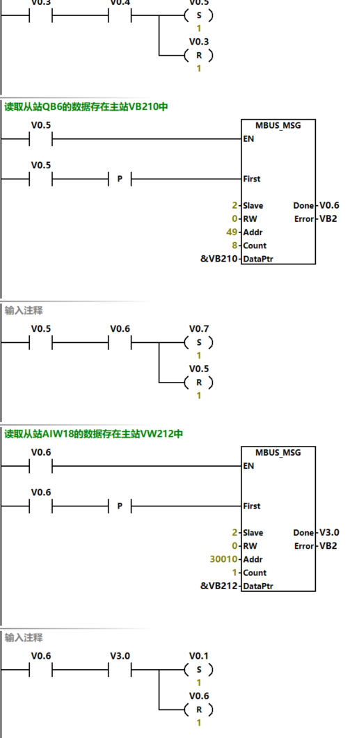
Figure 7: Master Station Data Read/Write Program
2. After completing the communication program, allocate 286 V storage areas for internal calculations, as shown in Figure 8.
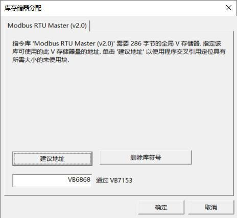
Figure 8: Allocating Storage Memory
3. After downloading the program for testing, connect one end of the hardware USB from Figure 2 to the computer, and the RS485 male connector to the CPU’s serial port; after connecting, check the specific COM port in the computer manager.
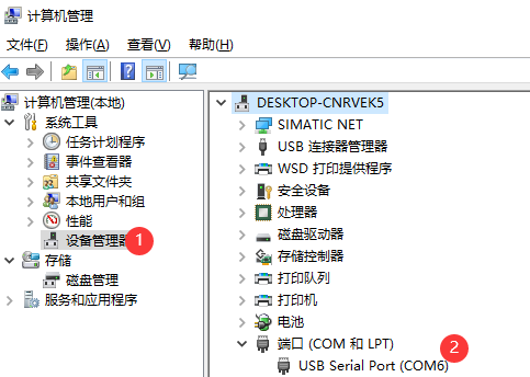
Figure 9: Viewing Port Number
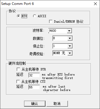
4. Open the Modsim32 debugging software, select the matching port in the connection settings as shown in Figure 10; after selecting the connection port, a protocol parameter setting dialog box will pop up, as shown in Figure 11. It is important to ensure that the communication parameters match those of the initialization command.
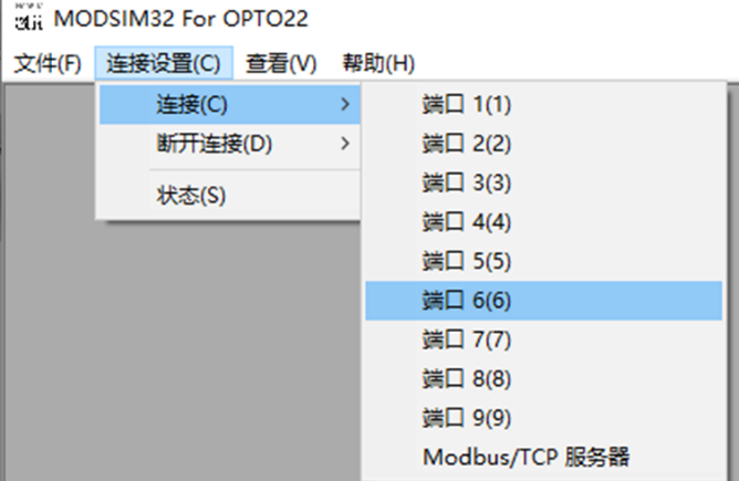 Figure 10: Connection Settings
5. In the “File” menu of Figure 10, select New, where device ID represents the slave address, set to 2.
The first group of data reads from the slave 40001 (VW300-VW308) starting with five consecutive words of data placed in the master station VW200 starting with five words; in the debugging software, writing data to the five consecutive words starting from 40001 will show that the monitored data from VW200-VW208 on the 200SMART side is the same, as shown in Figure 12.
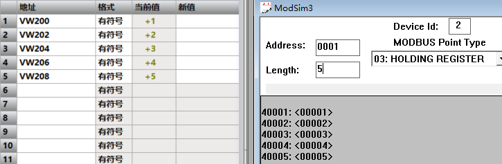
Figure 12: Data Exchange
The second group of data writes the status of eight consecutive bits from the master station I0.0 to the slave Q0.0; when I0.2 and I0.4 are forced, the statuses 0003 and 0005 from the slave are 1, as shown in Figure 13.
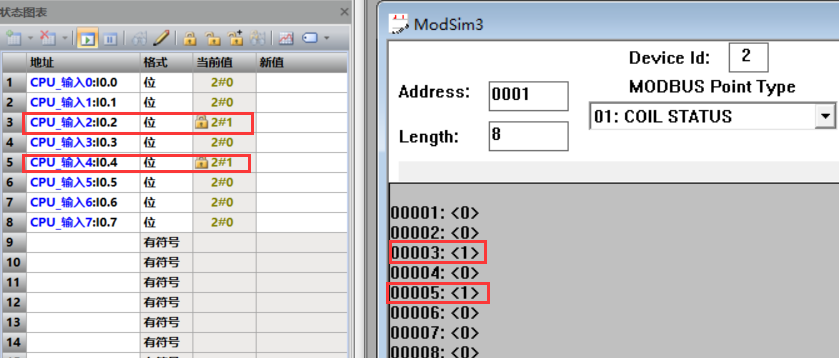
Figure 13: Data Exchange
The third group reads the data from the slave QB6 stored in the master station VB210; in the debugging software, setting Q6.0 and Q6.1 to 1 will result in the data of VB210 on the SMART side being 3, as shown in Figure 14.
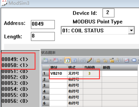
Figure 14: Data Exchange
The fourth group reads the data from the slave AIW18 stored in the master station VW212; after setting 30010 to the value of 457 in the debugging software, the data on the SMART side VW212 will be 457, as shown in Figure 15.
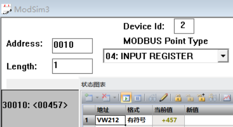
Figure 15: Data Exchange
Source: Technical Training Network, Author: Sui Xiangjian, reproduction without permission is prohibited~
Complete question bank for the 2023 Junior Electrician Exam (includes answers)
Three essential tools for electricians, easily accessible via WeChat!
[Collect] The “path” of a ten-year electrician, secrets to earning over ten thousand a month!
Which of the five major electrical drawing software (CAD, Eplan, CADe_sim…) do you pick?
The latest electrical version CAD drawing software, with a super detailed installation tutorial!
The latest electrical drawing software EPLAN, with a super detailed installation tutorial!
Common issues for beginners using S7-200 SMART programming software (includes download links)
Comprehensive electrical calculation EXCEL sheets, automatically generated! Electrical calculations made easy!
Bluetooth headsets, electrician/PLC introductory books available for free? Come and claim your electrical gifts!
Fundamentals of PLC programming: Ladder diagrams and control circuits (includes 1164 practical cases of Mitsubishi PLC)
Still can’t understand electrical diagrams? Grab the basics of electrician diagram reading and simulation software, and quickly get hands-on!
12 free electric worker video courses, 10GB of software/e-books, and 30 days of free electrician live classes are available!