DeviceNet Slave to Modbus Slave– ADFweb Gateway Converter– Guangzhou Xinyu IoT
Author: Zou Wuyi Mobile185-020-77899 Email[email protected]
1 Product Features:
Modbus Slave/ DeviceNet Slave Gateway has the following features:
- On the DeviceNet side, the maximum data read can reach 455 bytes, and the maximum data write can reach 455 bytes;
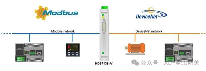
- Realizes bidirectional information transmission between the Modbus bus and the DeviceNet bus;
- Provides electrical isolation between the two buses;
- Power supply voltage range: AC 8…19 V (power consumption 4 VA) or DC 8…35 V (power consumption 4 W);
- Mounting on a 35mm DIN rail;
- Operating temperature range is -40°C to 85°C.
Configuration:
You need to install the Compositor SW67138 software on your computer to perform the following operations:
- Define parameters for Modbus;
- Define parameters for DeviceNet;
- Define read/write registers;
- Update firmware and/or projects.
2 New Project / Open Project: Click the “New Project” button to create a folder that contains the configuration information for the entire device. Device configuration information can also be imported or exported: To clone the configuration information of the programmable Modbus Slave to the DeviceNet Slave Gateway onto another device for configuration in the same way, you need to keep this folder and all its contents; To clone a project to obtain a different version of that project, simply copy the project folder and rename it, then click the “Open Project” button to open the new folder.
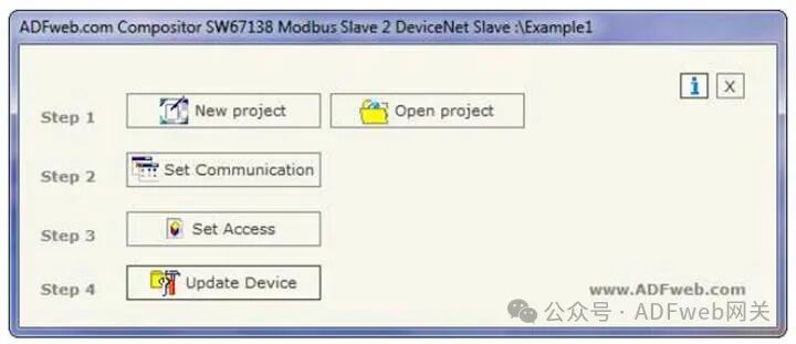
3 Set Communication:
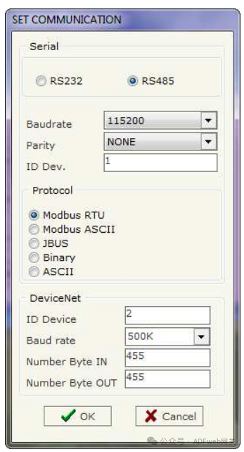
This section defines the basic communication parameters for the two buses (Modbus and DeviceNet).
After pressing the “Set Communication” button in the SW67138 main window (Figure 3), the “Set Communication” window (Figure 4) will pop up.
This window is divided into two parts, one for Modbus and the other for DeviceNet.
The meaning of the “Serial” field is as follows:
If the “RS232” field is checked, the serial line used is RS232; otherwise, if the “RS485” field is checked, the serial line used is RS485;
In the “Baud Rate” field, define the baud rate of the serial line;
In the “Parity” field, define the parity method of the serial line;
In the “Device ID” field, enter the Modbus Slave’s ID;
In the “Protocol” subsection, you can select the protocol you wish to use from the following:
• “Modbus RTU”;
• “Modbus ASCII”;
• “JBUS”;
• Simple “Binary” protocol;
• Simple “ASCII” protocol.
The meaning of the fields in the “DeviceNet” section is as follows:
In the “Device ID” field, define the gateway address for DeviceNet.
In the “Baud Rate” field, define the baud rate for DeviceNet;
In the “Input Byte Count” field, define the number of bytes from DeviceNet to the gateway (up to 455 bytes);
In the “Output Byte Count” field, define the number of bytes from the gateway to DeviceNet (up to 455 bytes).
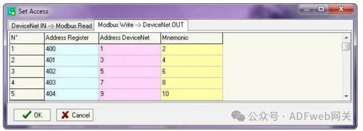
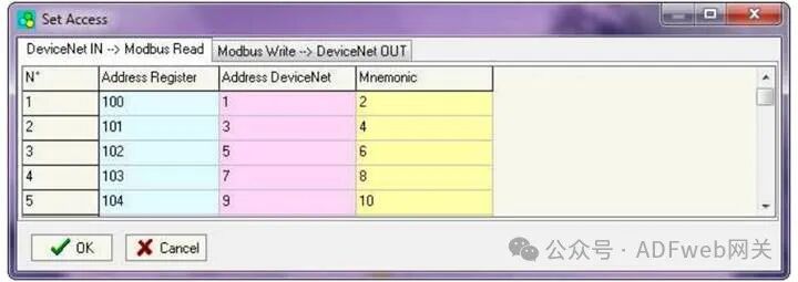
4 Set Access Rights: From the SW67138 main window (Figure 3), pressing the “Set Access Rights” button will pop up the “Set Access Rights” window (Figure 5). This window is divided into two parts, namely “DeviceNet Input –> Modbus Read” and “Modbus Write –> DeviceNet Output”. The first part (“DeviceNet Input –> Modbus Read”) allows the Modbus master to read data from DeviceNet. The second part (“Modbus Write –> DeviceNet Output”) allows the Modbus master to write data that can be read from the DeviceNet master.
DeviceNet Input –> Modbus Read field meanings are as follows: In the “Register Address” field, define the starting address of the register to be read; In the “DeviceNet Address” field, define the position in the DeviceNet array from which to read data; In the “Mnemonic” field, define the description of the request.
5 Modbus Write Operation –> DeviceNet Output
Field meanings are as follows:
• In the “Address Register” field, define the starting address of the register to be written;
• In the “DeviceNet Address” field, define the position where the data will be saved in the DeviceNet array;
• In the “Mnemonic” field, define the description of the request.