Click on the top “Technical Training” to select “Pinned Public Account”
Over 110,000 industrial control professionals follow this WeChat platform: Technical sharing, learning exchange, industrial control videos
Recently, many students have been asking about the MODBUS communication of the S7-200 series PLC, so today I will write an article to discuss how to use the MODBUS communication function of the S7-200 series PLC.
Overview of MODBUS Communication Protocol:
The MODBUS protocol is a universal protocol supported by many intelligent devices, such as frequency converters, intelligent temperature control instruments, etc.
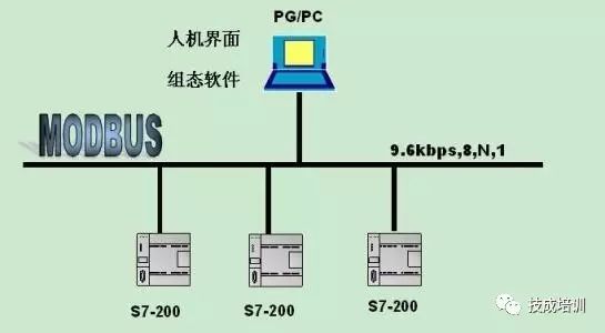
The MODBUS communication protocol includes MODBUS ASCII communication and MODBUS RTU communication over serial links, as well as MODBUS TCP communication based on TCP/IP. Here, we will mainly introduce MODBUS RTU communication over serial links.
Format of MODBUS RTU Information Frame:
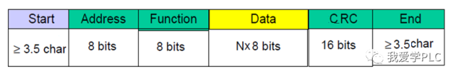
Start: The start code indicates the beginning of an information frame. In MODBUS RTU communication, time is used to indicate the start of the information frame, mainly by detecting the idle time on the transmission line, which lasts for 3.5 character times. The length of one character is related to data bits, stop bits, start bits, parity bits, and baud rate.
Address: The address code (one byte) indicates the station number of the slave device. The slave station number can be assigned or set by the slave device, such as a frequency converter, which can set its station number in its parameters.
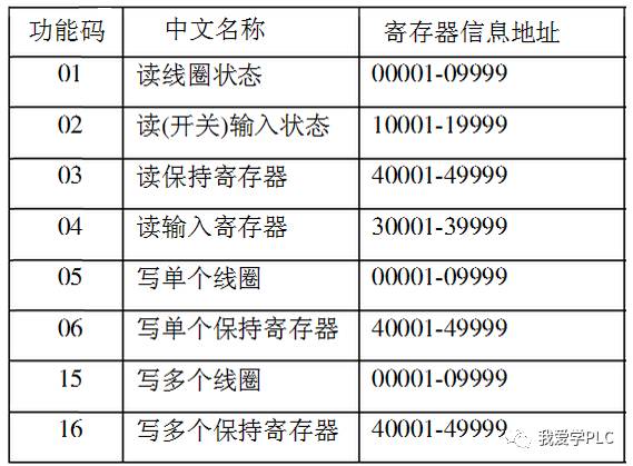
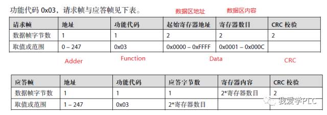
Function: The function code (one byte) describes the read/write operation on the slave, indicating whether to read data from or write data to the slave. Common function codes are shown in the figure below:
Data: The data area (N bytes) consists of two parts: one part is called the address of the data area, and the other part is called the content of the data area. For example, to control the operation of the frequency converter, the operation code of the frequency converter is called the content of the data area, and the place where the operation code needs to be written is called the address of the data area.
CRC: The checksum (2 bytes) performs a CRC check on the data from the slave number to the data area. You can refer to the previous article on CRC checksum program design for more information.
End: The end code, like the start code, is also determined by time.
Next, we will take the Siemens S7-200 SMART series PLC and the frequency converter from Shenzhen Haipumont as an example to illustrate how to use MODBUS communication to control the operation of the frequency converter, modify the frequency, and read some parameters.
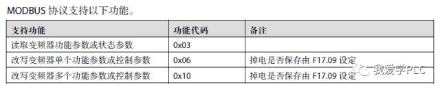
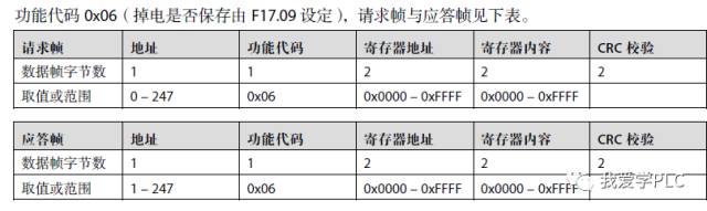
First, we need to familiarize ourselves with the communication content described in the frequency converter’s manual. The manual shows that the supported function codes are 03, 06, and 16 (Note: 0X10 represents the hexadecimal number 10).
The provided information frame format is:
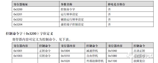
For example: to control the operation command, the address in hexadecimal is 3200. Writing different codes into address 3200 represents different control commands, as shown in the figure below.
Based on the above content, we can write the format of the information frame for controlling the operation of the frequency converter. Assuming the station number of the frequency converter is set to 1, we can derive the information frame format shown in the figure below.
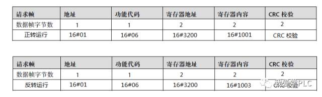
The information frame formats for other commands can be written in the same way by referring to the frequency converter’s manual.
Once the information frame format is established, the PLC can prepare the data according to the information frame format to send to the frequency converter. In the next article, I will mainly discuss the instructions used by the PLC to send this data.
Author: Zeng Xin. This article has been authorized for reproduction; please contact the author for permission.
Source WeChat ID: I Love Learning PLC
Share the experiences of the experts!
Click to read the original text to view the Siemens PLC Learning Tutorial
↓↓↓