Click↑↑Technical Training, follow and pin it to subscribe for free long-term
200,000+ industrial control personnel follow this WeChat platform: technical sharing, learning exchange, industrial control videos
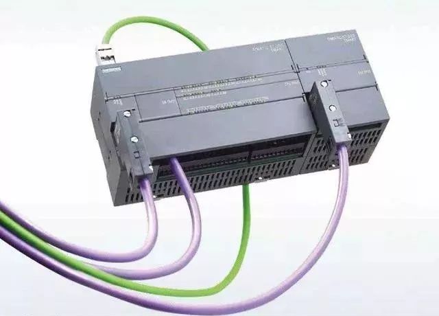
First, let’s introduce our hardware preparation
A weighing instrument that supports Modbus protocol
Weighing instrument that supports Modbus protocol
Set up the communication parameters of the instrument
You can adjust according to your requirements, as long as it is unified with the PLC side
Data format: 8n1: 8 data bits/no parity
Communication method: Modbus protocol
Instrument communication address: 1
Determine the variable address to be read
Here we only need to read the current real-time weight of the instrument
The address of the real-time weight of the instrument is 0, corresponding to 40001 in Modbus communication
Connect the RS485 interface A, B of the instrument to the DB9 interface of the PLC (DB9 interface 3 is A, 8 is B)
I remember 3 is A, 8 is B, not sure why this picture is like this, but it doesn’t matter, if different, just swap the two wires
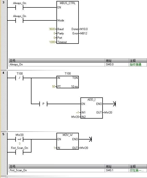
Preparation is complete, now we can start our PLC programming. Since the 200smart software itself has the Modbus protocol library, we do not need to add it separately, below is how to program.
Initialize master station command
The value entered for “Mode” is used to select the communication protocol. When the input value is 1, the CPU port is assigned to the Modbus protocol and this protocol is enabled.
The parameter “Parity” should be set to match the parity of the Modbus slave device. 0 (no parity)
The parameter “Port” sets the physical communication port (0 = integrated RS-485 in CPU).
The parameter “Timeout” is set to the number of milliseconds to wait for the slave to respond. A typical value is 1000 ms (1 s).
When the MBUS_CTRL command is completed, it returns “TRUE” to the “Done” output.
The “Error” output contains the result of the command execution.
The above parameter settings correspond to the weighing instrument side
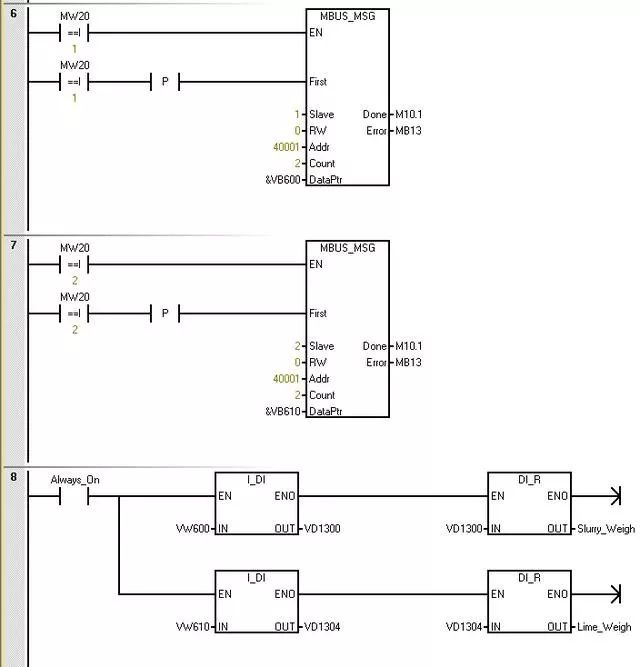
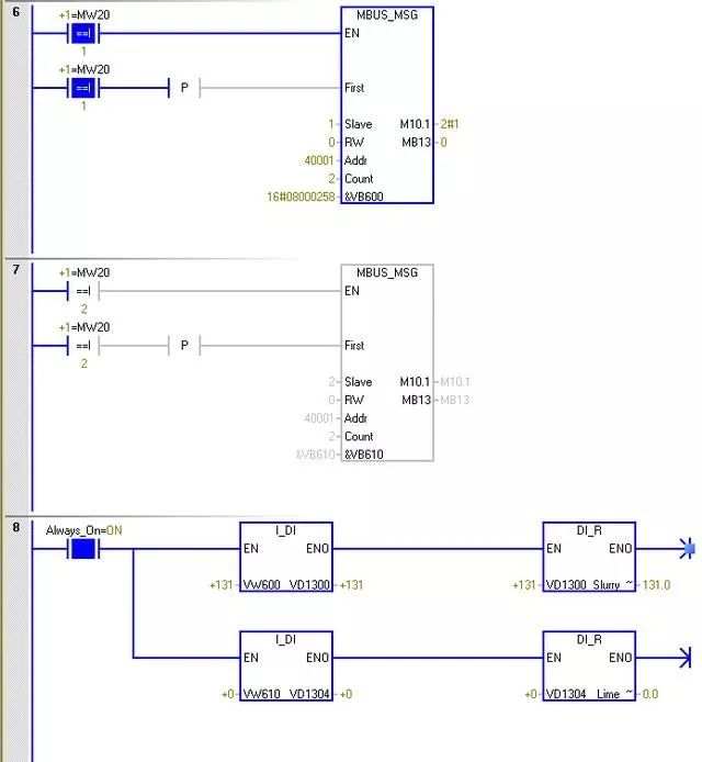
Polling access to two instruments
The parameter “Slave” is the address of the Modbus slave device. The allowed range is 0 to 247. Address 0 is the broadcast address. Only use address 0 for write requests. The system does not respond to broadcast requests to address 0. Not all slave devices support the broadcast address. The S7-200 SMART Modbus slave library does not support the broadcast address.
Use the parameter RW to indicate whether to read or write this message. 0 (read)
The parameter address (Addr) is the starting Modbus address. The register address is 0, corresponding to address 40001 in Modbus communication
The parameter “Count” is used to allocate the number of data elements to be read or written in this request. Read the number of holding registers in the instrument.
The parameter DataPtr is an indirect address pointer that points to the V memory in the CPU related to the read request. Set DataPtr to the first CPU storage unit for storing data read from the Modbus slave.
The data of the instrument at address 1 is stored in VW600, and the data of the instrument at address 2 is stored in VW610.
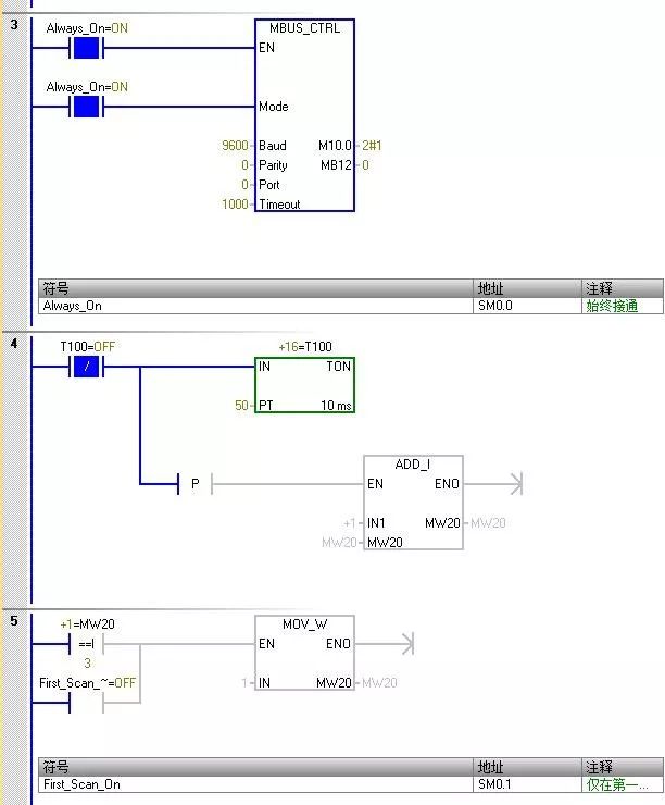
The programming is complete, now let’s see the monitoring effect.
The master initialization command runs normally, without errors
The data of the instrument at address 1 is 131, and the data of the instrument at address 2 is 0
This concludes our introduction to communicating with weighing instruments via the MODBUS library using the Siemens S7-200 SMART.
Source: Internet, copyright belongs to the original author, infringement will be deleted
If you like, remember to click “Looking“
Click↓Read the original text, for more electrical and PLC knowledge for free learning