Network Topology refers to the way in which various nodes (such as computers, printers, switches, etc.) are interconnected within a network. It determines the path of data flow and directly affects the network’s performance, reliability, and cost.
Network topologies are mainly divided into two categories: Physical Topology and Logical Topology. Physical topology refers to the actual, physical connections between devices; logical topology refers to the logical paths that data takes when transmitted across the network.
Here are several major types of network topologies:
1. Basic Topology Types
These are the core and fundamental structures, and more complex networks are usually combinations of these basic structures.
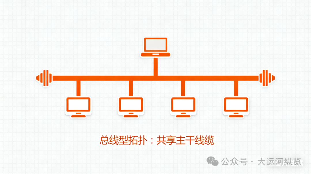
1. Bus Topology
· Description: All devices are connected to a single backbone cable (referred to as the bus).
· Operation: Data is sent onto the bus, and all devices can see the data, but only the device with the matching address will receive it. Terminators are required at both ends of the bus to absorb signals and prevent reflections.
· Advantages:
· Low cost: Simple wiring and minimal cable required.
· Easy to expand: Adding new devices is convenient.
· Disadvantages:
· Troubleshooting is difficult: A failure in any node or connector can cause the entire network to fail.
· Poor performance: All devices share bandwidth, and performance drops sharply under heavy load.
· Backbone failure is critical: If the backbone cable fails, the entire network is immediately disrupted.
· Common applications: Early Ethernet (10Base-2, 10Base-5), now rarely used.
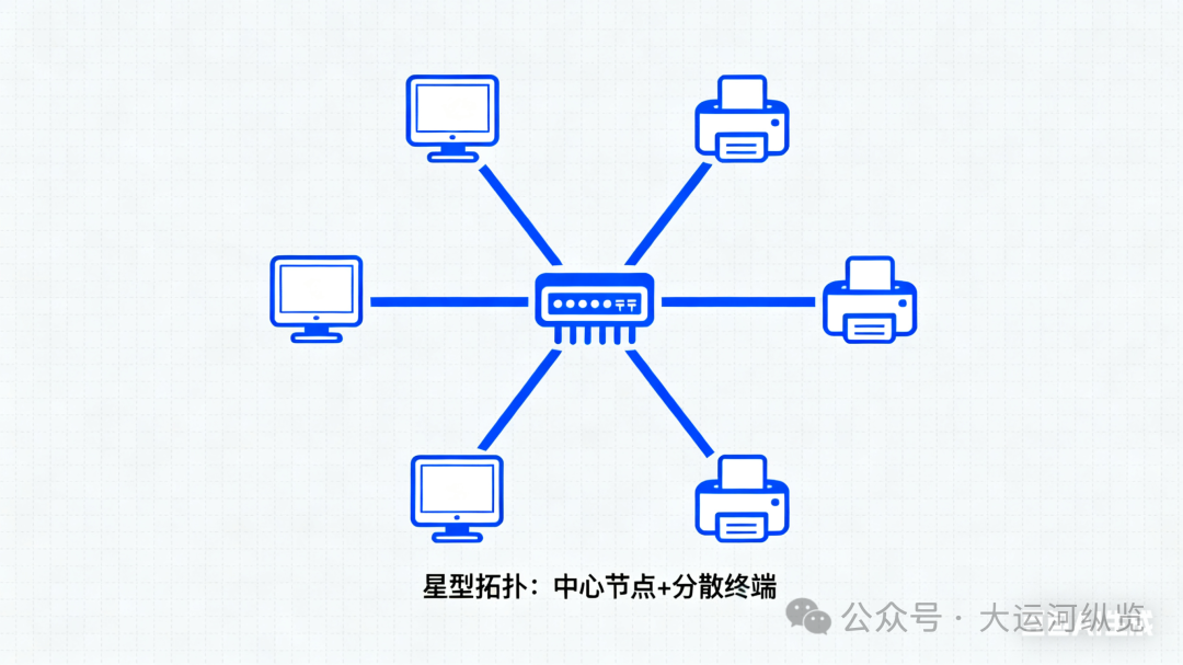
2. Star Topology
· Description: All network devices are directly connected to a central node (such as a switch or hub).
· Operation: Communication between any two devices must be forwarded through the central node.
· Advantages:
· Easy to manage and maintain: Faults are easy to isolate, and a failure in a single node or line does not affect the entire network.
· High stability: The central device is powerful, ensuring network stability.
· Easy to expand: Adding new devices does not affect the existing network.
· Disadvantages:
· Higher cost: Requires more cables and central devices.
· Central node is a single point of failure: If the central device (like a core switch) fails, the entire network will collapse. (Usually resolved through redundancy.)
· Common applications: This is currently the most common and mainstream local area network (LAN) topology, with modern Ethernet (homes, offices, internet cafes) almost universally adopting this structure.
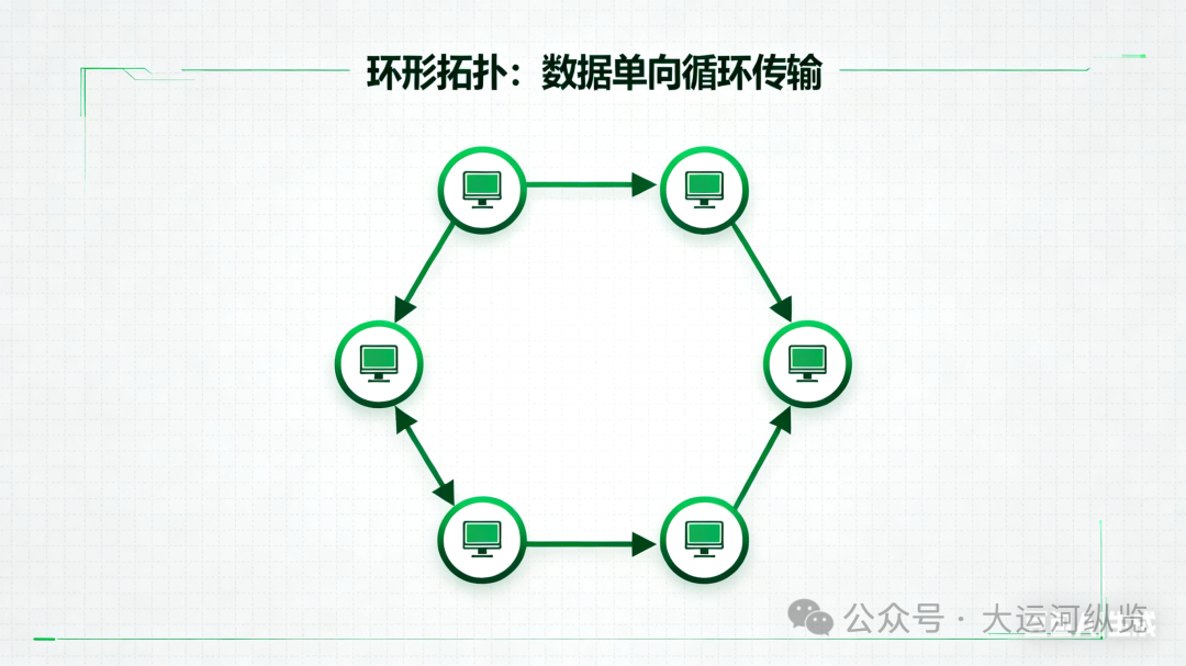
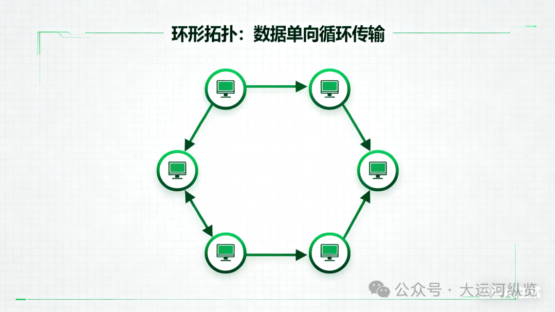
3. Ring Topology
· Description: Each device is directly connected to the two adjacent devices, forming a physical closed loop.
· Operation: Data is transmitted around the ring in one or both directions. Each device acts as a repeater, receiving and amplifying the signal to pass it to the next device.
· Advantages:
· Ordered transmission: No data collisions occur (Token Ring).
· Stable performance under load: Network performance does not significantly decline with an increase in users.
· Disadvantages:
· Poor reliability: A failure in any node or segment of cable will cause the entire network to fail.
· Difficult to expand and reconfigure: Adding or removing devices requires breaking the ring.
· Common applications: Token Ring, Fiber Distributed Data Interface (FDDI), now less common, mainly used in certain industrial networks or metropolitan area networks.
4. Mesh Topology
· Description: Devices are interconnected by multiple paths. It can be divided into full mesh and partial mesh.
· Full mesh topology: Every device is directly connected to every other device.
· Partial mesh topology: Only some devices are connected to multiple other devices to reduce complexity.
· Operation: Data can choose the optimal path for transmission from multiple paths.
· Advantages:
· Extremely high reliability: Multiple redundant paths ensure that a single point of failure does not affect communication.
· Easy fault diagnosis: Fault points are easy to locate.
· Powerful performance: Multiple paths share the load.
· Disadvantages:
· Extremely high cost: Requires a large amount of cabling and ports, installation and maintenance are complex.
· Common applications: Internet backbone, military networks, data center core layers, and other scenarios with high reliability requirements.
5. Tree Topology
· Description: A hierarchical structure resembling an inverted tree. It can be seen as an extension of star topology (multiple star networks cascaded together).
· Operation: At the top is a root node (core switch), connected below to multiple branches (aggregation layer switches), each branch then connects to multiple leaf nodes (access layer switches or terminals).
· Advantages:
· Easy to expand and manage: Clear hierarchy facilitates fault isolation and network management.
· Wide coverage: Can connect a large number of devices.
· Disadvantages:
· High dependency on the root node: A failure in the top-level root node can affect large portions of the network.
· Complex wiring.
· Common applications: Large enterprise networks, campus networks, the most commonly used extended topology in practice.
6. Hybrid Topology
· Description: A combination of two or more basic topological structures to leverage their advantages and avoid their disadvantages.
· Example: A school’s network may consist of multiple star topologies in classrooms and offices, connected by a bus-type backbone network, forming a “star-bus” hybrid topology.
· Advantages: Flexible, can meet complex practical needs, balancing reliability and cost.
· Disadvantages: Complex design and management.
· Common applications: Almost all large real-world networks are hybrid topologies.
Summary Comparison Table
Topology Structure | Advantages | Disadvantages | Typical Applications
Bus | Low cost, simple wiring | Difficult to troubleshoot, critical failure of backbone | Early networks, now obsolete
Star | Easy management, fault isolation, stable | Central node is a single point of failure | Modern LANs (absolutely mainstream)
Ring | Ordered transmission, no data collisions | Any node failure leads to network interruption | Token Ring, FDDI
Mesh | Extremely high reliability, multiple redundant paths | Extremely high cost, complex wiring | Internet backbone, data centers
Tree | Easy to expand, hierarchical management | High dependency on root node | Enterprise networks, campus networks
Hybrid | Flexible, balances reliability and cost | Complex design and management | Most large real-world networks
Physical Topology vs. Logical Topology
· Physical Topology: “How the wires are laid out.” Refers to the actual physical connection layout between devices. For example, a star physical topology using a hub.
· Logical Topology: “How the data flows.” Refers to the logical paths that data takes when transmitted across the network. For example, in the star physical topology mentioned above, due to the characteristics of the hub (broadcasting), it logically resembles a bus topology where all devices share bandwidth. If the central device is a switch, it logically operates in a point-to-point manner, closer to a star topology.
I hope this detailed explanation helps you fully understand network topologies!