
Control Requirement: Press the start button (I0.0 is ON), Q0.0 is ON; press the stop button (I0.1 is OFF), Q0.0 is OFF. The ladder diagram is shown in Figure 1.
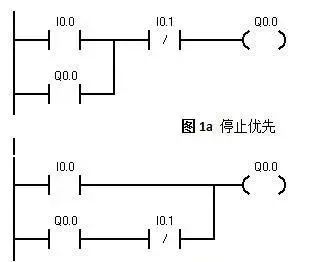
Figure 1: Start Priority
In the interlocking circuit shown in Figure 2, I0.0 and I0.1 are the start buttons, and I0.2 is the stop button.
In Figure 2(a), Q0.0 and Q0.1 are interlocked through the output; one must be powered on before the other can start, meaning it must be stopped before it can be started again.
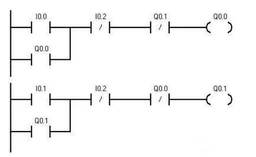 Figure 2(a)
In Figure 2(b), both the start and output are doubly interlocked.
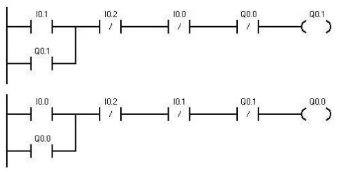
Figure 2(b)
Figure 3 shows a multi-location control circuit ladder diagram. I0.0, I0.1, and I0.2 are multi-location start buttons, while I0.3, I0.4, and I0.5 are multi-location stop buttons.
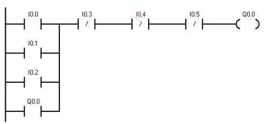 Figure 3
For example, with three motors, pressing the start button I0.0 will sequentially start motors Q0.0, Q0.1, and Q0.2; pressing the stop button I0.1 will sequentially stop motors Q0.0, Q0.1, and Q0.2. This program is widely used in sequential control of machinery such as belt conveyors. The sequential control ladder diagram is shown in Figure 4.
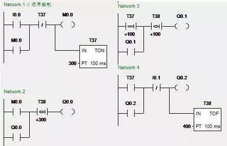
Figure 4
In the diagram, when starting, I0.0 is ON, using a time delay relay T37 to sequentially start the motors through comparison instructions. When T37’s current value equals 100, meaning after 10 seconds, Q0.1 starts, and after 20 seconds, Q0.2 starts. When stopping, I0.1 is ON, using a power-off delay relay T38 to sequentially stop the motors.
The frequency division circuit, also known as the single-button circuit, is needed in many control situations to divide the control signal. Sometimes, to save an input point, this circuit is also used. Figure 5 shows two ladder diagrams that achieve frequency division timing control.
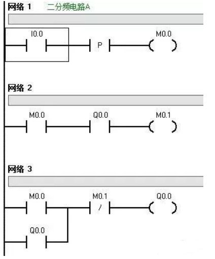 Figure 5(a)
In Figure 5(a), when the first pulse from I0.0 arrives, the PC scans for the first time, M0.0 is ON, Q0.0 is ON; during the second scan, M0.0 self-locks. When the second pulse arrives, the PC scans for the first time, M0.0 is ON, M0.1 is ON, Q0.0 disconnects; during the second scan, M0.0 disconnects, and Q0.0 remains disconnected; and so on.
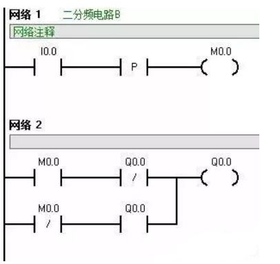 Figure 5(b)
The principle of Figure 5(b) is similar to that of the previous ladder diagram and will not be explained further.
This circuit is often used to control a lamp with two states using one button. Multiple input buttons can be connected in parallel below I0.0 to achieve multiple switches controlling one lamp.
The flashing circuit, also known as the oscillation circuit, is essentially a clock circuit that can have equal or unequal intervals of on and off.
In actual program design, if the circuit uses flashing functionality, it is often constructed using two timers or one timer to form the flashing circuit.
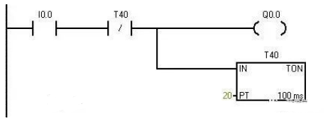
Figure 6(a)
Figure 6(a) is a simple flashing circuit control ladder diagram suitable for applications with low control precision. Figures 6(b) and 6(c) are two commonly used flashing circuit control ladder diagrams.

Figure 6(b)
This circuit starts working as soon as I0.0 is powered on, regardless of other signals. The on and off timing can be set as needed. Figure 6(b) is a flashing circuit control ladder diagram with a 2s on and 1s off timing.
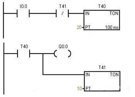
Figure 6(c)
Figure 6(c) is a flashing circuit control ladder diagram that is off for 2s and on for 1s.
Familiarity with the above control diagrams will greatly enhance the use of timers.
Disclaimer: This article is reprinted from the internet, and the copyright belongs to the original author. If there are copyright issues regarding the work, please contact us in time to delete it. Thank you!