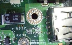
Common Faulty Components on PCBs
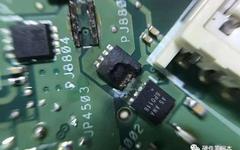
The failure caused by capacitor damage is the highest in electronic devices, especially with the failure of electrolytic capacitors being the most common. Capacitor damage manifests as: reduced capacity, complete loss of capacity, leakage, and short circuit.Capacitors play various roles in circuits, and the faults they cause are also characterized differently: in industrial control circuit … Read more