Source: ICisC Nanjing Integrated Circuit Industry Service Center
1. Choosing Pull-up Resistors for Microcontrollers
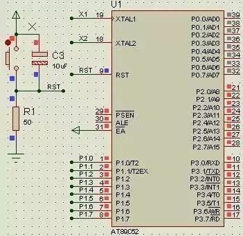
As can be seen in the reset circuit, when resistor R1=10k, RST is high, but when R1=50, RST is low. It is clear that R1=10k is incorrect, as the microcontroller remains in the reset state and cannot function at all. The reason for this is that the RST pin contains a transistor, which allows a small cutoff current to flow even when it is in the cutoff state. When R is very large, this weak cutoff current can create a high level.
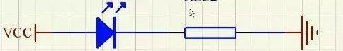
2. Calculating Series Resistors for LEDs
Typically, red surface-mount LEDs have a voltage of 1.6V-2.4V and a current of 2-20mA. Brightness changes at 2-5mA, and remains mostly unchanged above 5mA.
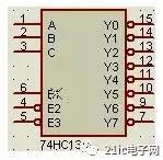
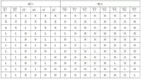
3. Insufficient Port Availability
In this case, you can use an expansion chip, such as the 74HC138 decoder for expansion.
4. Filter Capacitors
Filter capacitors can be divided into high-frequency and low-frequency filter capacitors.
1. High-frequency filter capacitors are typically 104 (0.1uF), aimed at short-circuiting high-frequency components to protect devices from high-frequency interference. Ordinary ICs should have these capacitors connected between power and ground to eliminate high-frequency noise (like electrostatic interference).
2. Low-frequency filter capacitors are generally electrolytic capacitors (100uF), used to remove low-frequency ripple, store some energy, and stabilize power supply. They are mostly connected at the power interface, near high-power components, such as USB ports, stepper motors, and 1602 backlit displays. The voltage rating should be at least twice the maximum system voltage.
5. The Role of Transistors
1. Switching Function:
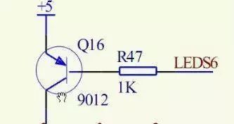
When LEDS6 is high, it is off; when low, it is on.
Calculation of the current-limiting resistor: If the collector current is I, then the base current is I/100 (this involves amplification; the collector current is 100 times the base current). The PN junction voltage is 0.7V, so R=(5-0.7)/(I/100).
2. Amplification Function:
The collector current is 100 times the base current.
3. Level Shifting:
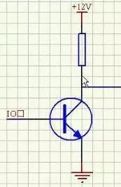
When the base is high, the transistor conducts, and the wire on the right connects to ground, creating a low level. When the base is low, the transistor is off, resulting in a high output level.
6. Issues Related to Seven-Segment Displays
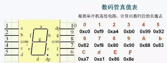
The numbers formed by lighting up the seven-segment display consist of segments a, b, c, d, e, f, g, and dp (decimal point), as shown in the truth table above.
7. Current and Voltage Driving Issues
Due to the limited output of microcontrollers, when there are many loads, a driver chip, such as the 74HC245, is needed.
8. Pull-up Resistors
Principles for Selecting Pull-up Resistors
● To save power and consider the chip’s current sinking ability, it should be sufficiently large; a larger resistor results in a smaller current.
● To ensure sufficient driving current, it should be sufficiently small; a smaller resistor results in a larger current.
● For high-speed circuits, excessively large pull-up resistors may cause the edges to become slower.
In summary: Common values for pull-up resistors are selected between 1K and 10K, and the same applies for pull-down resistors.
Pull-up and Pull-down Resistors
Pull-up means pulling an uncertain signal to high level through a resistor; pull-down works similarly.
● Level shifting, increasing output level parameters.
● An OC gate must have a pull-up resistor to function.
● Increases the driving capability of ordinary IO pins.
● Floating pins can be pulled up or down to resist interference.
9. Crystal Oscillator and Reset Circuit
Crystal Oscillator Circuit
● Crystal selection:
Select based on actual system requirements, such as 6M, 12M, 11.0592M, 20M, etc.
● Load capacitance:
Connect two capacitors of 10 to 30pF to ground, commonly using 20pF.
● Measuring crystal oscillators with a multimeter:
Directly connect the red probe to the crystal pins and the black probe to GND to measure voltage.
Reset Circuit
● Reset:
Sets the internal circuits of the microcontroller to a defined state, initializing all registers.
The reset time for the 51 microcontroller is about 2 machine cycles, but this depends on the chip datasheet.
Generally, this is done through a reset chip or reset circuit, with specific resistor-capacitor calculations found through Google.
10. Key Bounce and Elimination
Keys are also mechanical devices, and when pressed or released, they can produce bounce, as shown in the following images:
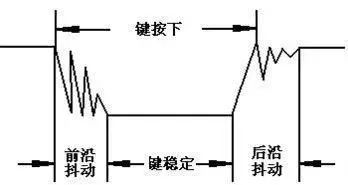
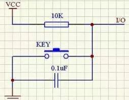
There are two methods to eliminate this: software debounce and hardware debounce, where hardware debounce uses capacitors to short-circuit high-frequency signals.
Software debounce detects the key closure and executes a delay routine, generating a 5ms to 10ms delay to allow the bounce to dissipate before checking the key state again. If the state remains closed, it confirms that the key is genuinely pressed.

Public Account ID: imecas_wx