1. Introduction
Originally, I needed to use the front end of the oscilloscope probe to create a shielded connection, but unexpectedly, when disassembling the front end, I discovered a strange part inside. It seems there is a small capacitor within this structure.
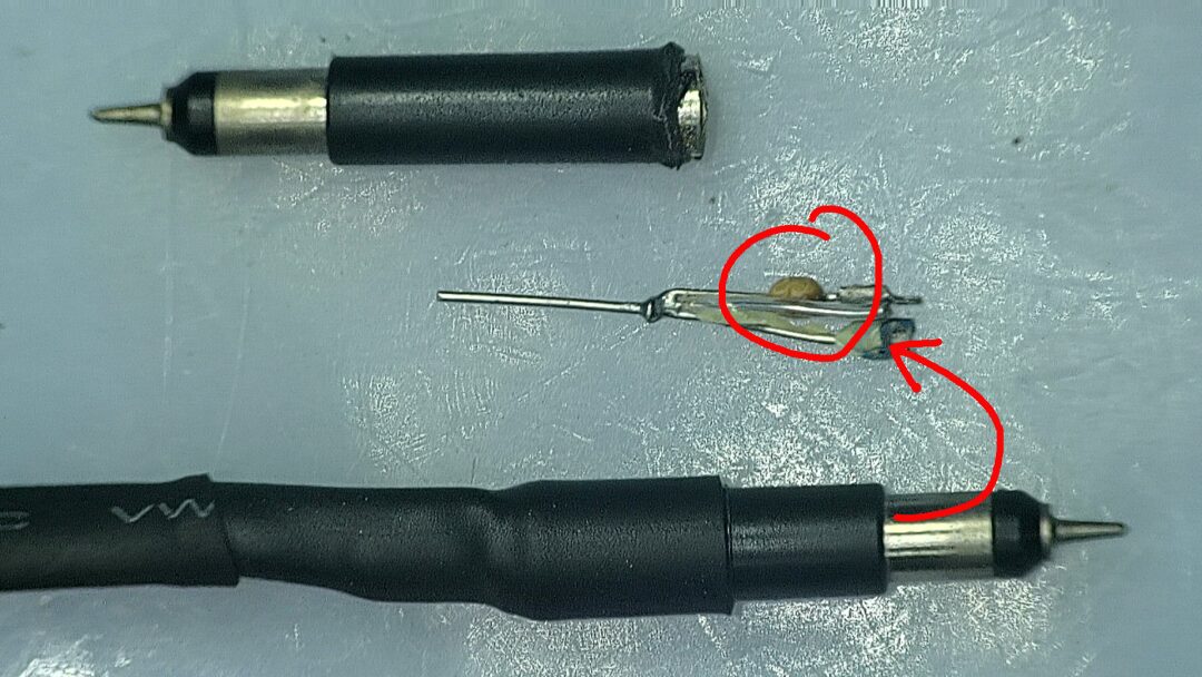
2. Internal Structure
To minimize the impact on the circuit being measured, the probe at the front of the oscilloscope is not directly connected to the circuit. Instead, it connects through a capacitor and a 9M ohm resistor to the shielded cable behind. In the structure I just disassembled, it can be seen that it includes a capacitor, and the resistor behind seems to have been cut during disassembly.
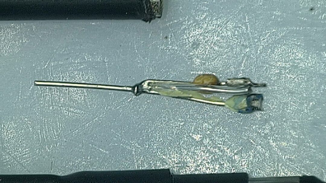
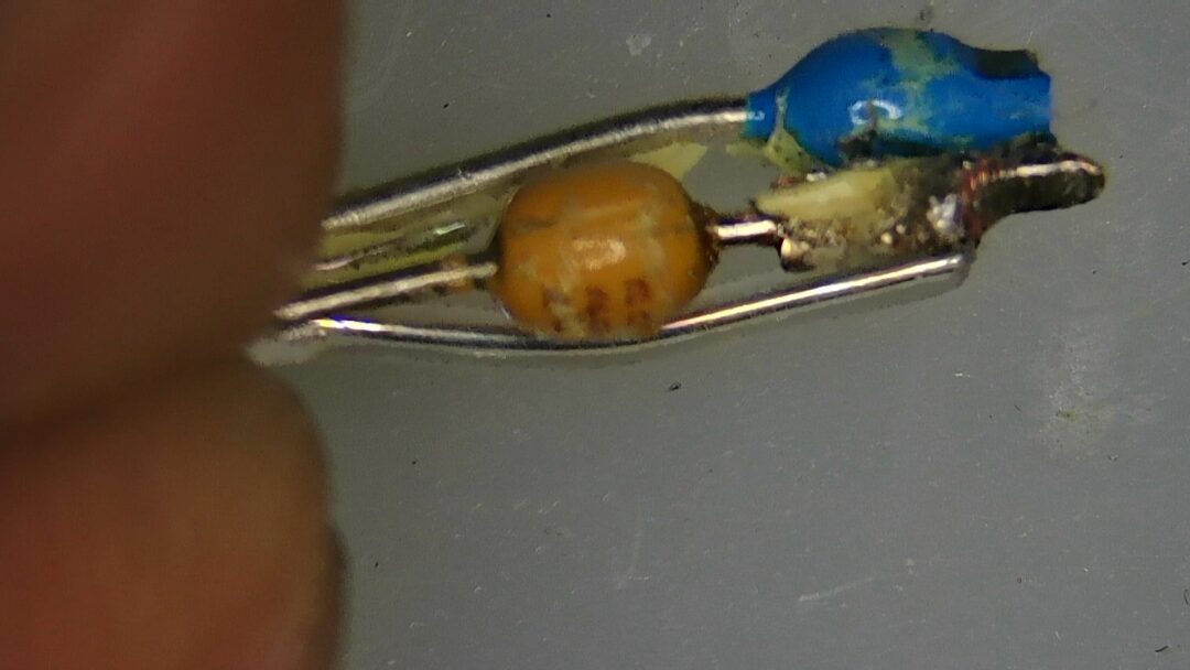
To be honest, seeing this raises some questions. Does adding such a capacitor and resistor for isolation significantly attenuate the signal? Using an LCR meter, I measured the coupling capacitor to be approximately 21pF. The resistor could not be measured since it was damaged.
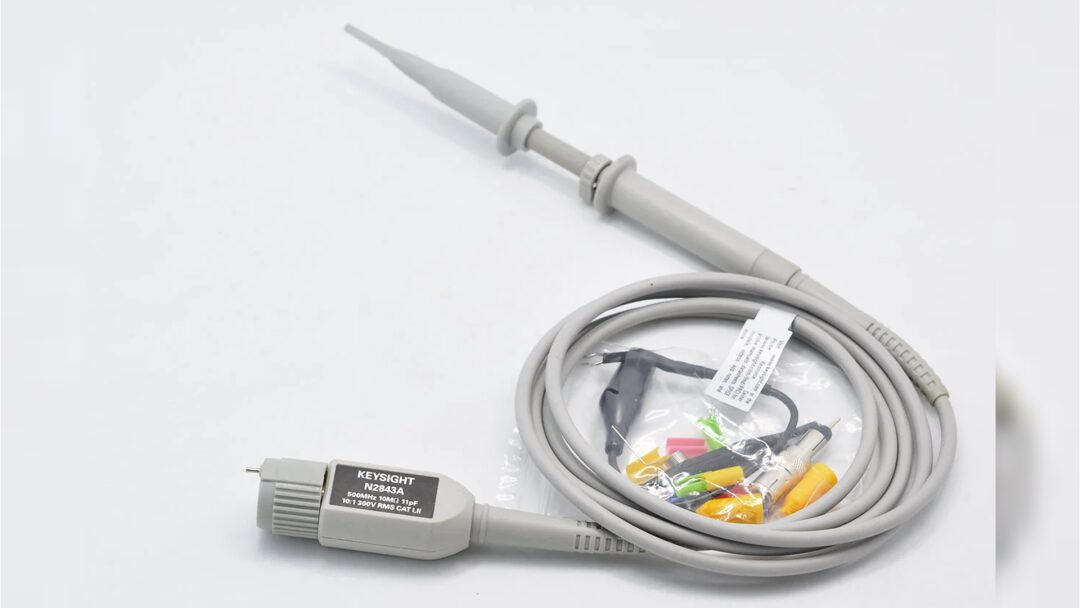
The isolation resistor and capacitor inside the oscilloscope probe are matched with the oscilloscope’s shielded cable. If the leads are opened, it can be seen that the wires inside the oscilloscope leads are very, very thin. This allows the characteristic impedance of the transmission line to reach 1M ohm.
※ Conclusion ※
This article observed the coupling capacitor and resistor inside an oscilloscope probe. The process of disassembly is recorded here.
