
Whenever a circuit board fails to operate normally, and the wiring checks out, it is very likely that an electronic component has failed. To repair it, you must identify the faulty component and replace it. However, locating the faulty component requires technical skills and certain techniques. Today, I will teach you how to use a multimeter to test some common electronic components.
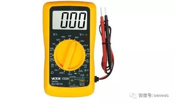
Multimeter
Testing Resistors
The most straightforward method to test a resistor is to use the resistance setting on the multimeter. Generally, the resistance value is marked on the resistor. Select the appropriate resistance range, connect the red and black probes to both ends, and if the reading is close to the marked value, it is normal; otherwise, it is faulty. When measuring high resistance, be careful not to touch the probes with both hands, not because it is dangerous, but to ensure the accuracy of the measurement. It is acceptable to touch one of the probes with your hand.
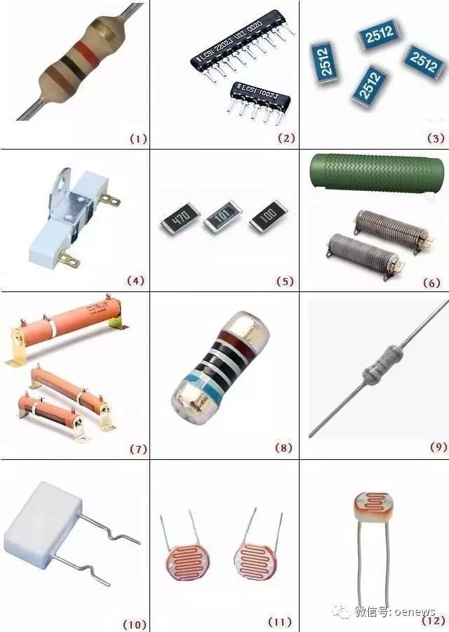
Resistor
Testing Potentiometers
Typically, a potentiometer has three pins. First, use the multimeter to select the resistance setting and test if the resistance between any two pins is equal to or close to the marked resistance value. If the difference is significant, the potentiometer is damaged. If it is normal, continue measuring these two pins, then rotate the potentiometer counterclockwise to the off position, at which point the resistance should be as low as possible. Then rotate it clockwise; if the resistance gradually increases and finally approaches the marked value, the potentiometer is normal.
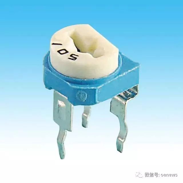
Potentiometer
Testing Fixed Capacitors
In addition to using the multimeter’s capacitor setting to measure the capacitor value, you can also use the resistance setting. Choose the appropriate resistance range, connect the two probes to the capacitor’s leads, and the resistance should be infinite. If the resistance reads 0, the capacitor is damaged.
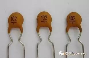
Fixed Capacitor
Testing Electrolytic Capacitors
Testing electrolytic capacitors is slightly different from fixed capacitors. Of course, you can choose to use the capacitor setting for testing, which is common knowledge. However, I will explain how to measure it using the resistance setting. First, select the appropriate resistance range, and connect the red and black probes to the two terminals of the capacitor. The displayed value will start from 0 and increase until it shows an overflow symbol (1). If it always displays 0, it indicates a short circuit inside the capacitor. If it always shows 1, it indicates an open circuit between the terminals. It is also possible that the resistance range selected is inappropriate. It is essential to note that since electrolytic capacitors have polarity, do not connect them in reverse. Typically, connect the red probe to the capacitor’s positive terminal (the longer lead) and the black probe to the negative terminal (the shorter lead). The needle multimeter is the opposite.
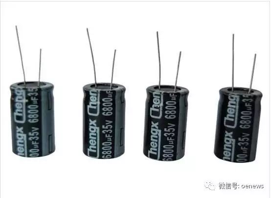
Electrolytic Capacitor
Testing Inductors
Similarly, select the resistance setting on the multimeter and connect the probes to both ends of the inductor. If the measured resistance is zero, it indicates a short circuit inside the inductor. Under normal circumstances, the DC resistance of the inductor being tested is directly related to the diameter of the enameled wire used to wind the inductor and the number of turns. As long as a resistance value can be measured, the inductor can be considered normal.
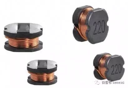
Inductor
Testing Diodes
Set the multimeter to the diode test setting. Connect the red probe to the anode of the diode and the black probe to the cathode. If the display shows the forward voltage drop of the diode (typically 0.5V for silicon diodes and 0.2V for germanium diodes), the diode is normal. Swap the probes; if the display shows 1, it is normal; otherwise, it is damaged. If both tests yield 0 or 1, the diode is faulty.
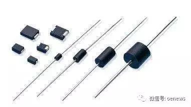
Diode
Testing LEDs
Similarly, set the digital multimeter to the diode test setting. Connect the red probe to the anode of the LED and the black probe to the cathode (just like the previous diode). If you see it light up, it is normal; otherwise, it is damaged.