In many circuits, small-value resistors are connected in series. Don’t underestimate them; they actually play a significant role.
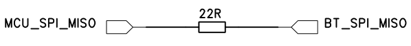
1. SPI Signal Lines
For SPI signals, the series resistor is generally around tens of ohms and has the following functions:
1) Impedance Matching. Since the impedance of the signal source is very low, and there is an impedance mismatch with the signal line, adding a resistor can improve the matching condition and reduce reflections.
2) The SPI rate is relatively high. Adding a resistor in series, along with the capacitance on the line and load capacitance, forms an RC circuit, which reduces the signal steepness and avoids overshoot. Overshoot can sometimes damage the chip’s GPIO, and it also benefits EMI, especially in high-speed circuits.
3) Convenient Debugging. Many current chips are in BGA or QFN packages. Adding a resistor in series makes it easier to capture waveforms with an oscilloscope during debugging.
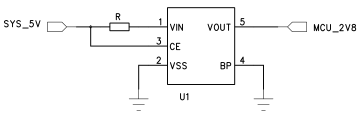
2. LDO Input Terminal
When the LDO’s VIN absolute maximum approaches the power supply voltage, and you do not want to replace it with a higher specification LDO to save costs, you can connect a small-value resistor in series. It can absorb part of the voltage and current. When a larger surge occurs at the power supply side, the resistor will take the hit first, at a lower cost.
If the LDO breaks down, and VIN and GND short circuit, the presence of the series resistor R will also prevent a short circuit between the power SYS_5V and GND.
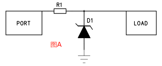
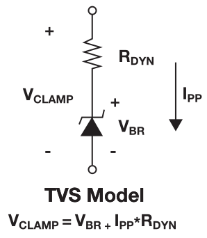
3. Series Resistors for TVS
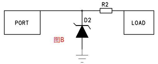
TVS series resistors generally have two connection methods: in Figure A, the resistor is before the TVS; in Figure B, the resistor is after the TVS. The two circuit usage scenarios are different.
First, let’s ask everyone a question: which has a stronger surge resistance, the resistor or the TVS? The answer is undoubtedly the TVS.
1) For Figure A, you must first consider the size of the surge. If it is not large, you can choose a resistor with suitable power. The resistor in front of the TVS will absorb a very small part of the current. After the surge current IPP decreases, the corresponding Vc (clamping voltage) of the TVS will also decrease, providing better protection for the downstream load.
2) For Figure B, the TVS first absorbs most of the surge current. Any residual voltage or current will pass through the resistor R2, performing secondary voltage division and current limiting, which can better protect the downstream load. If the downstream load is much larger than R2, the voltage division and current limiting will be negligible, and R2 will essentially have no effect.