Welcome FPGA engineers to join the official WeChat technical group.
Clickthe blue textto follow us at FPGA Home – the best and largest community for pure FPGA engineers in China.

The code comments are a bit rushed, please criticize any incorrect comments; it is for reference only.
UART
The UART is relatively simple, so only the tx section is commented in detail, but some content is still worth learning for beginners.
1 Start bit (low level) + 8 data bits + 1 stop bit (high level, here one period of high level is chosen, but two can also be used) (no parity bit)
1. Prescale is the number of clock counts needed to complete one bit (the relationship between this, the main clock, and the baud rate can be referenced in online articles).
2. It is best to synchronize the asynchronous signals entering the UART module using the provided synchronizer.
3. It is best to synchronize the asynchronous reset signal using the provided synchronizer.
4. The baud rate can be chosen arbitrarily as long as the clock is large enough to meet the bit error rate calculation; here, 125 MHz is used.
5. The basic idea is to shift.
6. The transmission condition is handshaking.
7. If using Xilinx chips, it is recommended to use global clock resources (the method of connecting IBUFG to BUFG is the most basic way to use global clock resources).
8. This complete code uses IBUFG + BUFG.
9. Although the transmission is simple, there are still many knowledge points worth learning for beginners.
10. The public account only provides simple comments on the code.
UART Transmission Data Module
// Welcome to follow the public account: AriesOpenFPGA// QQ group: 808033307// Language: Verilog 2001
// The code comments are a bit rushed, please criticize any incorrect comments; it is for reference only.
// UART
// 1 Start bit + 8 data bits + 1 stop bit (no parity)
// Prescale is the number of clock counts needed to complete one bit (the relationship between this, the main clock, and the baud rate can be referenced in online articles).
// It is best to synchronize the asynchronous signals entering the UART module using the provided synchronizer.
// It is best to synchronize the asynchronous reset signal using the provided synchronizer.
// The baud rate can be chosen arbitrarily as long as the clock is large enough to meet the bit error rate calculation; here, 125M is used.
// The basic idea is to shift.
// The transmission condition is handshaking.
// If using Xilinx chips, it is recommended to use global clock resources (the method of connecting IBUFG to BUFG is the most basic way to use global clock resources).
// This complete code uses IBUFG + BUFG.
// Although the transmission is simple, there are still many knowledge points worth learning for beginners.
// The public account only provides simple comments on the code.

timescale 1ns / 1ps
/* AXI4-Stream UART */
module uart_tx #(
    parameter DATA_WIDTH = 8
)(
    input  wire                   clk,           // System clock
    input  wire                   rst,           // Reset signal
    /* AXI input */
    input  wire [DATA_WIDTH-1:0]  s_axis_tdata,  // Data to be sent
    input  wire                   s_axis_tvalid, // Data is ready to be sent
    output wire                   s_axis_tready, // This module is ready to receive data
    output wire                   txd,           // UART interface
    output wire                   busy,          // Status line busy
    input  wire [15:0]            prescale       // Configuration prescale
);

reg s_axis_tready_reg = 0;
reg txd_reg           = 1;
reg busy_reg          = 0;

reg [DATA_WIDTH:0] data_reg = 0;
reg [18:0] prescale_reg     = 0;
reg [3:0] bit_cnt           = 0;

assign s_axis_tready = s_axis_tready_reg;
assign txd           = txd_reg;
assign busy          = busy_reg;

always @(posedge clk) begin
    if (rst)         begin
        s_axis_tready_reg <= 0;  // Slave not ready to send
        txd_reg           <= 1;  // Transmission line high
        prescale_reg      <= 0;  //
        bit_cnt           <= 0;  // Bit counter initialized to 0
        busy_reg          <= 0;  // Not busy after reset
    end else         begin
        if (prescale_reg > 0)                 begin
            s_axis_tready_reg <= 0;
            prescale_reg      <= prescale_reg - 1;
        end else if (bit_cnt == 0)     // Bit counter is 0
            begin
                s_axis_tready_reg <= 1;   // Slave raises ready signal
                busy_reg          <= 0;   // Busy signal low
                if (s_axis_tvalid)        // If slave is ready to receive data
                    begin
                        s_axis_tready_reg <= !s_axis_tready_reg;   //
                        prescale_reg      <= (prescale << 3)-1;    //
                        bit_cnt           <= DATA_WIDTH+1;         // Count 10 times
                        data_reg          <= {1'b1, s_axis_tdata}; //
                        txd_reg           <= 0;                    // Start bit 0 (start bit tx low, stop bit high)
                        busy_reg          <= 1;                    // Enter busy state after starting transmission
                    end
            end else                 begin
                if (bit_cnt > 1)   //
                    begin
                        bit_cnt             <= bit_cnt - 1;
                        prescale_reg        <= (prescale << 3)-1;  // After (prescale << 3)-1 clock counts, complete one bit shift
                        {data_reg, txd_reg} <= {1'b0, data_reg};   // Shift operation
                    end                     else if (bit_cnt == 1)                          begin
                        bit_cnt      <= bit_cnt - 1;
                        prescale_reg <= (prescale << 3);
                        txd_reg      <= 1;                // Stop bit 1
                    end
            end
    end
end
endmodule
UART Reception Module (not explained in detail)
// Language: Verilog 2001
`timescale 1ns / 1ps
/* * AXI4-Stream UART */
module uart_rx #(
    parameter DATA_WIDTH = 8
)(
    input  wire                   clk,
    input  wire                   rst,
    /* AXI output */
    output wire [DATA_WIDTH-1:0]  m_axis_tdata,
    output wire                   m_axis_tvalid,
    input  wire                   m_axis_tready,
    /* UART interface */
    input  wire                   rxd,
    /* Status */
    output wire                   busy,
    output wire                   overrun_error,
    output wire                   frame_error,
    /* Configuration */
    input  wire [15:0]            prescale
);

reg [DATA_WIDTH-1:0] m_axis_tdata_reg = 0;
reg m_axis_tvalid_reg = 0;
reg rxd_reg = 1;
reg busy_reg = 0;
reg overrun_error_reg = 0;
reg frame_error_reg = 0;

reg [DATA_WIDTH-1:0] data_reg = 0;
reg [18:0] prescale_reg = 0;
reg [3:0] bit_cnt = 0;

assign m_axis_tdata = m_axis_tdata_reg;
assign m_axis_tvalid = m_axis_tvalid_reg;
assign busy = busy_reg;
assign overrun_error = overrun_error_reg;
assign frame_error = frame_error_reg;

always @(posedge clk) begin
    if (rst) // Initialize various parameters
        begin
            m_axis_tdata_reg <= 0;
            m_axis_tvalid_reg <= 0;
            rxd_reg <= 1;
            prescale_reg <= 0;
            bit_cnt <= 0;
            busy_reg <= 0;
            overrun_error_reg <= 0;
            frame_error_reg <= 0;
        end     else         begin
            rxd_reg <= rxd;
            overrun_error_reg <= 0;
            frame_error_reg <= 0;
            if (m_axis_tvalid && m_axis_tready) // Data ready to send and ready to be sent
                begin
                    m_axis_tvalid_reg <= 0;
                end
            if (prescale_reg > 0) //
                begin
                    prescale_reg <= prescale_reg - 1;
                end                     else if (bit_cnt > 0)             begin
                if (bit_cnt > DATA_WIDTH+1)                     begin
                    if (!rxd_reg)  // Actual read is 0, start counting bits
                        begin
                            bit_cnt <= bit_cnt - 1;
                            prescale_reg <= (prescale << 3)-1;  // Prescale is 16 bits shifted 3 bits minus 1 bit, because prescale_reg
                        end                         else                             begin
                            bit_cnt <= 0;
                            prescale_reg <= 0;
                        end
                end                                 else if (bit_cnt > 1)                     begin
                    bit_cnt <= bit_cnt - 1;
                    prescale_reg <= (prescale << 3)-1;
                    data_reg <= {rxd_reg, data_reg[DATA_WIDTH-1:1]};
                end                                 else if (bit_cnt == 1)                     begin
                    bit_cnt <= bit_cnt - 1;
                    if (rxd_reg)                             begin
                        m_axis_tdata_reg <= data_reg;
                        m_axis_tvalid_reg <= 1;
                        overrun_error_reg <= m_axis_tvalid_reg;
                    end                         else                             begin
                        frame_error_reg <= 1;
                    end
                end            end         else             begin
                busy_reg <= 0;
                if (!rxd_reg)                 begin
                    prescale_reg <= (prescale << 2)-2;
                    bit_cnt <= DATA_WIDTH + 2;
                    data_reg <= 0;                       busy_reg <= 1;
                end            end                    end
end
endmodule
UART Top Level
// Language: Verilog 2001
`timescale 1ns / 1ps
/* * AXI4-Stream UART */
module uart #(
    parameter DATA_WIDTH = 8
)(
    input  wire                   clk,
    input  wire                   rst,
    /*     * AXI input     */
    input  wire [DATA_WIDTH-1:0]  s_axis_tdata,
    input  wire                   s_axis_tvalid,
    output wire                   s_axis_tready,
    /*     * AXI output     */
    output wire [DATA_WIDTH-1:0]  m_axis_tdata,
    output wire                   m_axis_tvalid,
    input  wire                   m_axis_tready,
    /*     * UART interface     */
    input  wire                   rxd,
    output wire                   txd,
    /*     * Status     */
    output wire                   tx_busy,
    output wire                   rx_busy,
    output wire                   rx_overrun_error,
    output wire                   rx_frame_error,
    /*     * Configuration     */
    input  wire [15:0]            prescale
);

uart_tx #(
    .DATA_WIDTH(DATA_WIDTH))uart_tx_inst (
    .clk(clk),
    .rst(rst),
    // axi input
    .s_axis_tdata(s_axis_tdata),
    .s_axis_tvalid(s_axis_tvalid),
    .s_axis_tready(s_axis_tready),
    // output
    .txd(txd),
    // status
    .busy(tx_busy),
    // configuration
    .prescale(prescale));

uart_rx #(
    .DATA_WIDTH(DATA_WIDTH))uart_rx_inst (
    .clk(clk),
    .rst(rst),
    // axi output
    .m_axis_tdata(m_axis_tdata),
    .m_axis_tvalid(m_axis_tvalid),
    .m_axis_tready(m_axis_tready),
    // input
    .rxd(rxd),
    // status
    .busy(rx_busy),
    .overrun_error(rx_overrun_error),
    .frame_error(rx_frame_error),
    // configuration
    .prescale(prescale));
endmodule
Synchronizer (Asynchronous Reset) Module
// Language: Verilog-2001
// A commonly used module
`timescale 1 ns / 1 ps
/* * Synchronizes an active-high asynchronous reset signal to a given clock by * using a pipeline of N registers. */
module sync_reset #(
    parameter N=2 // depth of synchronizer
)(
    input wire clk,
    input wire rst,
    output wire sync_reset_out);

reg [N-1:0] sync_reg = {N{1'b1}};
assign sync_reset_out = sync_reg[N-1];

always @(posedge clk or posedge rst) begin
    if (rst)        sync_reg <= {N{1'b1}};
    else        sync_reg <= {sync_reg[N-2:0], 1'b0};
end
endmodule
Synchronizer (Asynchronous Signal) Module
// Language: Verilog-2001
// A commonly used module
`timescale 1 ns / 1 ps
/* * Synchronizes an asynchronous signal to a given clock by using a pipeline of * two registers. */
module sync_signal #(
    parameter WIDTH=1, // width of the input and output signals
    parameter N=2 // depth of synchronizer
)(
    input wire clk,
    input wire [WIDTH-1:0] in,
    output wire [WIDTH-1:0] out);

reg [WIDTH-1:0] sync_reg[N-1:0];
/* * The synchronized output is the last register in the pipeline. */
assign out = sync_reg[N-1];
integer k;

always @(posedge clk) begin
    sync_reg[0] <= in;
    for (k = 1; k < N; k = k + 1) begin
        sync_reg[k] <= sync_reg[k-1];
    end
end
endmodule
Welcome FPGA, embedded, signal processing engineers to follow the public account.

National No. 1 FPGA WeChat Technical Group
Welcome to join the national FPGA WeChat technical group, which has tens of thousands of engineers, a group of engineers who love technology, where FPGA engineers help each other and share knowledge, creating a strong technical atmosphere!Quickly gather your friends to join!!

Press and hold to join the national FPGA technical group.
FPGA Home Component City
Advantageous component services, please scan the code to contact the group owner: Jin Juan Email: [email protected] Welcome to recommend to procurement
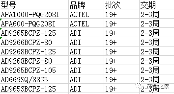
ACTEL, AD part of advantageous ordering (operating a full series):
XILINX, ALTERA advantageous stock or ordering (operating a full series):
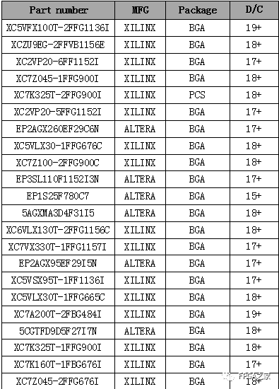
(The above components are part of the models, for more models please consult group owner Jin Juan)
Service philosophy: FPGA Home component self-operated city aims to facilitate engineers to quickly and conveniently purchase component services. After years of dedicated service, our customer service is spread across major domestic listed companies, military research units, and small and medium-sized enterprises. Our biggest advantage is emphasizing service first, and achieving fast delivery and favorable prices!
Direct brands: Xilinx ALTERA ADI TI NXP ST E2V, Micron and more than a hundred component brands, especially good at components under US embargo against China.Welcome engineer friends to recommend us to procurement or consult us personally!We will continue to provide the best service in the industry!

FPGA technical group official thanks to brands: Xilinx, intel (Altera), microsemi (Actel), Lattice, Vantis, Quicklogic, Lucent, etc.